w w w . d e l l . c o m s u p p o r t . d e l l . c o m
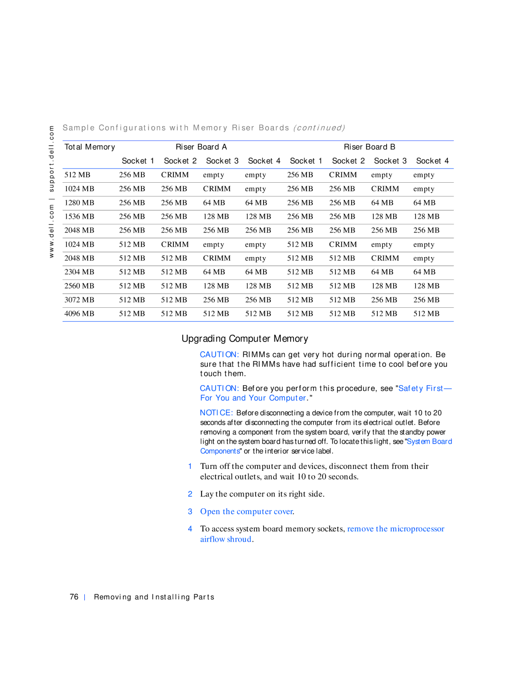
S a m p l e C o n f i g u r a t i o n s w i t h M e m o r y R i s e r B o a r d s ( c o n t in u e d )
Total Memory |
| Riser Board A |
|
| Riser Board B |
| ||
| Socket 1 | Socket 2 | Socket 3 | Socket 4 | Socket 1 | Socket 2 | Socket 3 | Socket 4 |
|
|
|
|
|
|
|
|
|
512 MB | 256 MB | CRIMM | empty | empty | 256 MB | CRIMM | empty | empty |
|
|
|
|
|
|
|
|
|
1024 MB | 256 MB | 256 MB | CRIMM | empty | 256 MB | 256 MB | CRIMM | empty |
|
|
|
|
|
|
|
|
|
1280 MB | 256 MB | 256 MB | 64 MB | 64 MB | 256 MB | 256 MB | 64 MB | 64 MB |
|
|
|
|
|
|
|
|
|
1536 MB | 256 MB | 256 MB | 128 MB | 128 MB | 256 MB | 256 MB | 128 MB | 128 MB |
|
|
|
|
|
|
|
|
|
2048 MB | 256 MB | 256 MB | 256 MB | 256 MB | 256 MB | 256 MB | 256 MB | 256 MB |
|
|
|
|
|
|
|
|
|
1024 MB | 512 MB | CRIMM | empty | empty | 512 MB | CRIMM | empty | empty |
|
|
|
|
|
|
|
|
|
2048 MB | 512 MB | 512 MB | CRIMM | empty | 512 MB | 512 MB | CRIMM | empty |
|
|
|
|
|
|
|
|
|
2304 MB | 512 MB | 512 MB | 64 MB | 64 MB | 512 MB | 512 MB | 64 MB | 64 MB |
|
|
|
|
|
|
|
|
|
2560 MB | 512 MB | 512 MB | 128 MB | 128 MB | 512 MB | 512 MB | 128 MB | 128 MB |
|
|
|
|
|
|
|
|
|
3072 MB | 512 MB | 512 MB | 256 MB | 256 MB | 512 MB | 512 MB | 256 MB | 256 MB |
|
|
|
|
|
|
|
|
|
4096 MB | 512 MB | 512 MB | 512 MB | 512 MB | 512 MB | 512 MB | 512 MB | 512 MB |
|
|
|
|
|
|
|
|
|
Upgrading Computer Memory
 CAUTION: RIMMs can get very hot during normal operation. Be sure that the RIMMs have had sufficient time to cool before you touch them.
 CAUTION: Before you perform this procedure, see "Safety First— For You and Your Computer."
NOTICE: Before disconnecting a device from the computer, wait 10 to 20 seconds after disconnecting the computer from its electrical outlet. Before removing a component from the system board, verify that the standby power light on the system board has turned off. To locate this light, see "System Board Components" or the interior service label.
1Turn off the computer and devices, disconnect them from their electrical outlets, and wait 10 to 20 seconds.
2Lay the computer on its right side.
3Open the computer cover.
4To access system board memory sockets, remove the microprocessor airflow shroud.
76