Comdial
Table of Contents System Overview
Table Of Contents IMI 66-r
Installation
FCC Rules and Regulations
Class of Service Programming
System Programming
Data Communications with the Digitaltelephone System
Attendant Station Operation
System Operating Procedures -l
System OPERATlNG Characteristics
Station Operation -l
List of Tables
List of Illustrations
System Overview
Systemoverview
General Information
Section Publications Overview Manual Scope
Related Publications
System Overview IMI
Spkr Hold Itcm
Common Equipment DESCRlPTlON
Station Description
Model CO/PBX Station Capacity
Available in both monitor and speakerphone versions
+-I
Ggt cnzm
System Overview
D33 System Overview
Park Orbits Speed Dials System Station Autodials
Section General Specifications
KEY System
Dysrem Overview
Description of System Features
Automatic Hold Transfer to Line
Automatic Dialing
Automatic Hold for Intercom
Automatic Hold Transfer to Intercom Answer Hold
Call Announce with Handsfree Answerback
Battery BACK-UP CHASSIS, CABLE, and Batteries
Block Programming
Background Music External Music Source RE 6 Uired
Call Pickup Directed
Call Forwarding on ALL Calls
Call Forwarding Personal
Call Park
Call Transfer Unscreened
Class of Service Programming From Main Station
Class of Service Programming Video Display Terminal
Class of Service Program Printout
Conferencing ADD-ON
Default Functional Program
Default Toll Restriction
Delayed Ringing
Dial 0 for System Al-l-ENDANT
DESIGNATtIK?d&AMMABLE
Direct Inward Station Dialing Disd
Ion Of System Features
Do not Disturb
Flexible Station and Line Class of Service Control
END-TO-END Signalling On Intercom
Exclusive Hold SYSTEM-WIDE ENABLE/DISABLE
Feature Inhibit
Handsfree Answer Inhibit
Programmability of Features
Intercom Line Timeout
Flexible Station Numbering Plan
LCD Support
Line Access Restriction
Line Answer from ANY Station Night Mode
LCD Messaging
Power Failure Transfer
Modular Wiring and JACKSR- or Conductor Wire System
MUSIC-ON-HOLD SYSTEM-WIDE ENABLE/DISABLE
Pooled Line Access Group Line Access
Saved Number Redial
Any other station port hrrt be m tothem
Originate BUlTON
Secure OFF-HOOK Voice Announce Sohva Groups
Blocked
Speakerphone Support
Self Diagnostics
Service Observing
SQUARE/NON-SQUARE Configuration
Subdued Ringing Timed Hold Recall
System Alarm Reports
Tenant Service
Toll Restriction Night Mode
Voice Mail Transfer on Busy
Tone or Voice Signalling Intercom
Unanswered Call Transfer Recall Timing
Voice Announce Blocking
Mounting Considerations
Installation
Section Standard Installation Details
Mounting Procedure
Mounting Dimensions
= 1 + 0 N
AC Power Connection
Battery BACK-UP
System Grounding
External Ibattery
Fuse
~COMDIAL
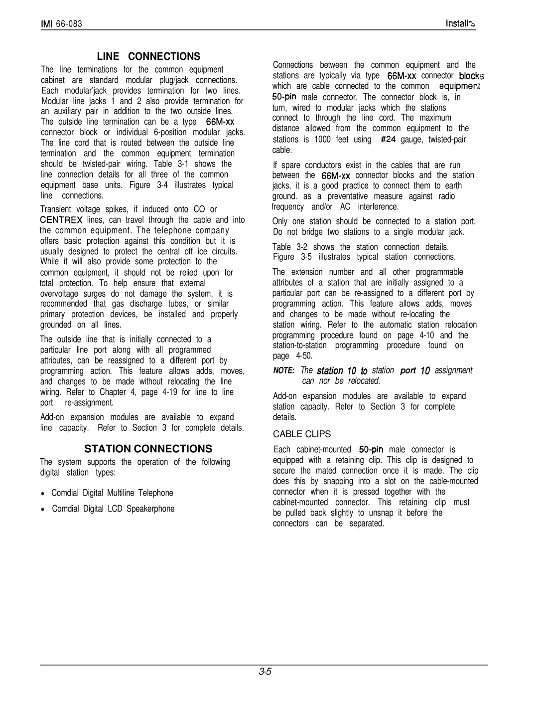
Line Connections
Station Connections
Cable Clips
TIP
Spare Ports
J-l Statlon Connections Line, &Station Base Unit
Wire Color PAI STA
Spare Ports
Iii Ii0
Connections
I32
Line Station Base Unit
WfKJi
Installat
Clip Terminals
KEY SYSTEM/HYBRID Configuration
Line Group Including Dial Access
111 z 442 r ,I z
Power Failure Station Connections
Installa
Power Failure Terminals on Station Connector Block
AtJXILIARY Equipment Interface
Ilon
Flgurs 3-8. Auxiliary Interface Connections
Directly to the 117VAC Line
Common Audible and Auxiliary Ringinginterface
AndRlV
Aon IMI
Overrides the ring pattern closure provided
Special transformer-isolated paging port is used to
IMI Installa
External Paging Interface Line Port
MDlvIaJJK 6-fosrrlom
None
Order
Send Data
Base Unit
Installat
For Music on tii&DFND Background
Music Interface
Itrion
Music Source
Section ADD-ON Expansion Modules Introduction
IMI Instalk
Line Connections 408 Expansion Module No Connection
3%STATIONS
Installation
Statlon Connections 408 Expansion Module
Installation
Mstallat/$n
Pull module down to latch in place
To remove a cartridge
Installation
To install a cartridge
Section
16. Software Cartridge lnstallatlon and Removal
Installation
Position
Communication Procedures
Section Data Communications with Digital Telephone System
Equipment Required
Interconnect Cable
Flgure 3-17. Data Communlcatlons Interconnection Diagram
Common Equipmen
Telephone Jack Data Jack
Failure Isolation
Section System Checkout and Failure Isolation
Initial Condition
Check OUT
No.004-000-00345-4
System Programming
Section General Information
Programming Overlays
System’Programming
Section Class of Service Programming
Typical Feature Programming Sequence
Dial a feature code to select a programming parameter
Dial + # 7 4 6 +k COW/G. Mode
Base Level The first step in any
Master Clear n
Line Default
System Defaults
CONFIG. Mode
System Default
Fnanswered Call Transfer Recall
Systemconfiguration
Description
Iystem Defauft The system
Feature Description Entry Code and Prompting Display
Reference Record
Delete Statlon Message Detall
AccountingSMDArecordsby
Xxxxxxxx w
EATUFlE Description
Never Recall
Press Spkr to end
Default = Disable
Randem Attendant When this
System Alarm Reportlng Special
Alarm Report
Default = ALL Enabled
Zone Paglng
Press Itcm +k # 7 4 6 +k for base level
Press Itcm +K # 7 4 6* for base level
Feature
‘A Options
Rlnglng Tracking Relay
Al4 15,16 Hold plus Al A8 17-24
Line Configuration
Line Default
Line PROG. Buttons Keypad Buttons
Portientr
Feature Description
Idefault = no Line Names Assigned
Hxlliaty Llnes a line port can be Dial
Line Groups on next
Line groups are
Group 3 = Dial
Group 4 = Dial
Pulse Dial
‘EATURE Description
Code Prompting Display Reference Record
NE Group
Department
Feature Description
Default = 50 Msec
Hold Release
LOG/CAL Line
Privacy Release
Assign Logicauphys
Phys Latch
Model Line
Block Programmlng
BLK Programming
Select model line port with keypad
Iii
Description Entry Code and Prompting Display
Station Configuration
Statlon Default The station
STA Keypad Buttons
Deptx WYY
Access Code
Assign EXT. NUM
DEPT. Calling
Port Entry
3EFERENCE Record
FNTRY Code and Prompting Display
An be provided with busy override. This
5YS SPD Toll RST
Station FEATURES’
FIT
Iport IRY! PQ
Station 10 57 Dial 10
Dial+N for next station feature
Default = not Assigned
Ports to be programmed
Select station ports to be programmed Station 10 57 Dial 10
Ring Line Pref
Auto Hold
Station Features
Press Itcm % # 7 4 6 +# for base level
Wtomatlc
147
Headset Mode
‘EATURE Description Entry Code and Prompting Display
Ringing Tone
Press Itcm ++ # 7 4 6 % for base level
Ntercom
Press Spkr to end
= None Assigned
Features
Press Itcm ++ # 7 4 6 % for base level
Direct Department Calllng Stations
Assigned WitIon Message Detail Account
Iefault = no
Entry Code and Prompting Display Reference Record
Call Forward On BusylRlng No
Secure Off-Hook Voice Announce
Isohva Dlsable The Sohva feature
Default = Sohva Enabled AT ALL STA
Off-Hook Voice Announce
Port Entry !PORT! Fntryi
Default = not Assigned
Ill-Call
Eature
312
Not Assigned
3a. Assign prime line
Station Features
Stailine Config
Prime Line
Station Ports 10
Delay Ring
Code and Prompting Display Eference Record
Ring
Wvacy Release a line can be made Dial
Stmine Config
Access Deny
Press Itcm +k # 7 4 6 +k for base level
Idle Llne Preference With idle line
Press Itcm +k # 7 4 6 ++ for base level
‘EATURE Description
Origination Deny
System hogramming
STATION/LINE Configuration Record
‘EATURE Description Entry Code and Prompting Display
Press Al A14, Bl
Pr Y Itcm % # 7 4 6 ++ for base level
Eature Description
Lnes To Buttons
BU77ON Mapping ’
See Chart on
Button Mapping ’
Assign 2ND Itcm ’
Page
Page
Page
Page
Code Button Press
Press Itcm % # 7 4 6 + for base level
Jne Group Queue Button a station
PressAl A14, Bl
NON Square System Reference Record
IMI System Programming z
Station Namf Station Location
PressSPKR10end.J
Default = Logical Same AS Physical
I36
Jport 10 = STA 10, ETC
Disable STATION!3
On a per station basis Select station ports to be disabled
Dial 10 Dial +k for configuration mode
Default = no Stations Disabled
SFC
Direct Inward Station Dialing Disd
Base Level The first step in any
Dlal Tlme
Disd Assist Nite
Default = 0 Rings
Default = STA IO DAY and Night
Disd Assist DAY STA Mght STA UMS AS 1 GM2
Transfer of Voice Mall
Voice Mall Llne ID When ExecuMail
Analogterminalinterface
Press Itcm 3F # 7 4 6 t for base level
ATI
Press Itcm ++ # 7 4 6 +k for base level
Lolce Mall Transfer on Busy When
Thru
I57
Default = not Enabled
Voice Mall Port Connect
ATI Dlstlnctlve Rlnglng Intercom
Toll Restriction Table Configuration
System, list them on one or two tables
Several tables
Press Itcm Dial t # 7 4 6 +k
Default Toll
Xxxxxx
Xxxxx Table Y
Allow Table Y
Deny Table Y
None AS’GND
Sign Toll Table To Station Dial
Dial 01 16 for toll tables 1-16 to be as’gnd to sta
Assign TOLL-NITE
Toll Restriction Programming Reference Tables
S t e m Pronramrriina ’
Data Printer Service
Zone Call Band Tables Long Distance Calls
Integrated Call Costing
Exception Tables Local Calls and Long Distance Calls
Office Code Band Tables Local Calls
Discard Digits
Area Code Band Table Long Distance Calls
Area co& band tables are the m
Call Rate Tables Local and Long Distance Calls
11 Costing Diagram
Dial 01- 33 for call rate table number
3ase Level The first step in any PresslTCM%#7466
To entries in the call cost
Dial 1 to assign the call rate table Anbe made
Press Itcm ++ # 7 4 6* for base level
Press Itcm * # 7 4 6 % for base level
Icharge R2RATF Surcharge
Cost T&U
Last
Resort
Ratf Surcharge
Dial Time
Smda Programming
Answer Time
Deptx Yyyy
Press Itcm ‘Ik # 7 4 6 * for base level
Eight numbers
Lat category or grouping can be
Worded. An account code can be a
Three numbers and a
MAXACCT. Code
Disable Outgoing
Press Itcm +k # 7 4 6 ‘Ik for base level
Account Codes
To program for Smdr prlntout
‘EATURE Description
Ro program Smdr cost repoftlng
XXXXXXXCOST/NG
Attendant Configuration
Dial 91 94 for line group l-4
Press Itcm +k #I 7 4 6 % for base level
Iystem Speed Dial
Entry Code and Prompting Display Ieference Record
System Speed Dial Record
LCD Messaglng a message can be
Feature Description Entry Code and Prompting DISPLAY’
Xxxxxxx Yyywyy
# 7 4 6 t for base level
Statlon Names
Xxxxxx
Introduction
VDT Programming Procedure
Section Video Display Terminal Programming
Introduction
Typical PC Operation
Procedure
Installation
Remote Programming
Up-Load COS Data From Computer To Common Equipment
Type 2 then press Enter
Press page UP
’3. Remote Programming Block Diagram
System COS Menu Selections
Menu Descriptions
IMI System Programming s
Main Menu Selections
COlPABX Typical line connection
Line C.O.S. Programmlng
Line COS Menu Selections
Assign Area Codes / Prefixes to Bands
Station C.O.S. Programming
Station COS Menu Selection
AC . . . . . . .... All Call
Toll Restriction Table Administration
A10 Al2 Al? All Bl8283
Station 10 Programming Overlay
Station 10 Programming Overlay
PPOl3-100 A10
All
66 B7
Station Operation Answering Calls
Systemoperatingprocedures Section
Voice Calling
Line Group Access
Outside Line Calling
Intercomcalling
Automaticdialing
Speed Dialing
Automatic Redialing
Transferring Calls
Holding Calls
FIVE-PARTYCONFERENCE
Conferencing
Messaging
Unscreened Transfer
Line Monitoring
Voice Announce Blocking
Paging
RECALL/FLASH
Background Music
PULSE/TONE Switching
Mute / Handsfree Answer Inhibit
Personal Ringing Tones
Call Forward ALL
Call Forward
Automatic CALL-BACK
Call Waiting
Outgoing Call
Service Observing
Executive Override
Account Code Operation
Autodial Programming
Speakerphone Operation
Departmental Station Operation
Station User Programming
Programming Response Message Button
Station Speed Dial Programming
Direct Station SELECTION/BUSY Lamp Field Dswblf Programming
Programming Automatic Redial Button
Programming Secure OFF-HOOK Voice Announce Originate Bull-ON
Programming Assist BUlTON Press Itcm 4+ ++
Press Itcm Dial +l+ # 0
System Clock
System Speed Dial Programming
System Bperation
Station Names
On when music on hold is provided and turn off
Music on Hold
LCD Messaging
Character Codes
System Alarm Reporting
Station Message Detail Accounting Smda Printout
Direct Inward Station Dialing
Controls and Indicators
Rm4,Ext
Section System Operating Characteristics
Feature Dialing Code Numbering Plan Dialing Codes
HarmuP
BktCk BbCk
Feature Dialing Codes
Numbering Plan
Saved Number
Display Intensity
Ringer Volume Control
Status Indicators and Tone Sequences
To adjust the display Intensity
Sjlstem Gperation
Heard through handset receiver or over monitor speaker
Continuously Nlgnttransfer feature Not allowed
Ohva
Line Select Lights
Active Messaging
Continuous flutter Msec. on 70 msec. off
Message Wafting Continuous flash 560 msec. on 560 msec. off
Steady on with wink off Sec. on 70 msec. off Auto
IMI System OpeWion
Maintenance
Technical AS~M&tAt$E and Repair
Comdiai
Wall Plate Or-#10 Screws 15/l
Maintenance
Index
Publication Index
DSS/BLF
Index
IMI Index
Jmspeed~
Index
Readers Comment Form
Comdial Technical Publications Department
Charlottesville VA
Postage will be Paid by Addressee
Programmlng Per-Station Smda
Feature and Benefit
Base Unit Product Code
Smda Reporting
VDT COS Progrw
Feature Benefits
Account Codes and Emergency Numbers
Featurebenefits
TAB
Account Code Message Display Time
Benefits Account Codf Featu
Station 10 Programming !caSJ
Dta
Feature
Benefits VDT COS Progrb
Enter COS programming
T C O S P R O
Ount Des
To return to the previous menu during programming
Account Codes Support for Caller ID Service
Benefits
To display a list of stored emergency numbers
Caller ID Unit
Feature Benefits
Cross Connects
DIgiTech CommonEquipmeni
YDT PROGRAMMlW
Benefits Station 10 PRO
Er ID cont. VDT Progr
Featurebenefits
Noans
Enhanced automatic call back
Feature and Benefit
Software release 10 provides the following enhancements
Benefit
Simplified hybrid operation
Hz @ 16 Hz warble
666/571 Hz @ 23 Hz warble
@ 23 Hz warble
Featurebenefit
Direct Ring
Voice MAlL Port
Automatic AlTENDANT Optlon
Stmine
Feature
Support for ExecuMall voice processing system
Benefit
Press Spkr to end Voice Mail Transfer on Busy Optlon
Feature Benefit
‘qlpport for
Voice Mail Line ID Optlon
PPO13-100
38-39
Ksue T a B 0 8
Date Juiy
48-49
Console Feature
BENEFITt
DigiTech Software Enhancement
Clarificationdescription
VDT Programming
Benefit Station 10 Programming
Programming Clarification
Programmed
Programming OVERLAY, DD32X
PAMD-PORT
Paired Port Console Spare