2 Installation
This section of the manual will cover basic installation information.
2.1 Mechanical Installation
Please refer to the Installation Sheet that comes with the
2.2 Slot Selection
The
2.3 Electrical Connections
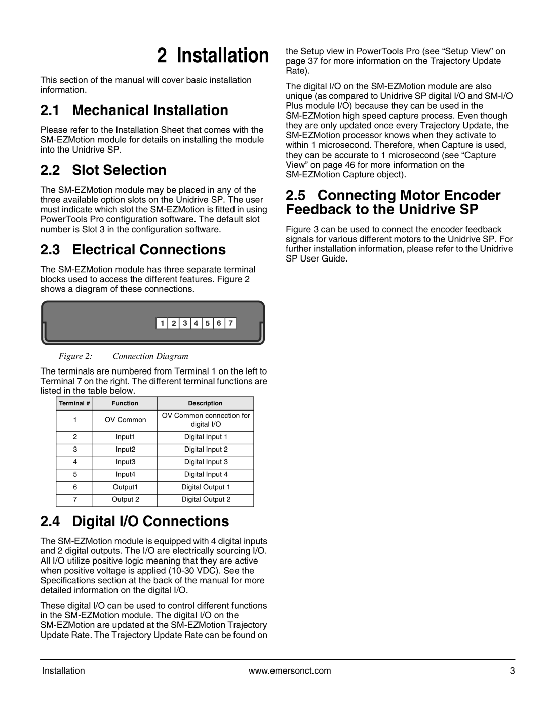
The
1 2 3 4 5 6 7
Figure 2: Connection Diagram
The terminals are numbered from Terminal 1 on the left to Terminal 7 on the right. The different terminal functions are listed in the table below.
Terminal # | Function | Description | |
|
|
| |
1 | OV Common | OV Common connection for | |
digital I/O | |||
|
| ||
|
|
| |
2 | Input1 | Digital Input 1 | |
|
|
| |
3 | Input2 | Digital Input 2 | |
|
|
| |
4 | Input3 | Digital Input 3 | |
|
|
| |
5 | Input4 | Digital Input 4 | |
|
|
| |
6 | Output1 | Digital Output 1 | |
|
|
| |
7 | Output 2 | Digital Output 2 | |
|
|
|
2.4 Digital I/O Connections
The
These digital I/O can be used to control different functions in the
the Setup view in PowerTools Pro (see “Setup View” on page 37 for more information on the Trajectory Update Rate).
The digital I/O on the
2.5Connecting Motor Encoder Feedback to the Unidrive SP
Figure 3 can be used to connect the encoder feedback signals for various different motors to the Unidrive SP. For further installation information, please refer to the Unidrive SP User Guide.
Installation | www.emersonct.com | 3 |