Control Loop | Modbus | Task 0 |
| Control Loop | Modbus | Task 1 |
| Control Loop | Modbus | Task 2 | Control Loop | Modbus | Task 3 |
|
|
|
|
|
|
|
|
|
|
|
|
|
|
|
|
|
|
|
|
|
|
|
|
|
|
|
|
Update Rate | Update Rate | Update Rate | Update Rate |
![]() = Control Loop Update
= Control Loop Update
![]() = Modbus messages
= Modbus messages
![]() = Control Loop Update
= Control Loop Update
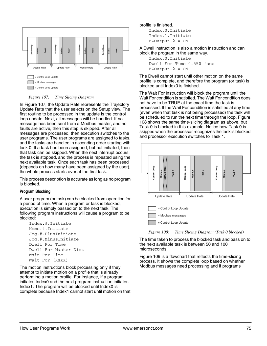
Figure 107: Time Slicing Diagram
In Figure 107, the Update Rate represents the Trajectory Update Rate that the user selects on the Setup view. The first routine to be processed in the update is the control loop update. Next, all messages will be handled. If no message has been sent from a Modbus master, and no faults are active, then this step is skipped. After all messages are processed, then execution switches to the user programs. The user programs are assigned to tasks, and the tasks are handled in ascending order starting with task 0. If a task has been assigned, but not initiated, then that task can be skipped. When the next interrupt occurs, the task is stopped, and the process is repeated using the next available task. Once each task has been processed (depends on how many have been assigned by the user), the whole process starts over at the first task.
This process description is accurate as long as no program is blocked.
Program Blocking
A user program (or task) can be blocked from operation for a period of time. When a program or task is blocked, execution is simply passed on to the next task. The following program instructions will cause a program to be blocked:
Index.#.Initiate
Home.#.Initiate
Jog.#.PlusInitiate
Jog.#.MinusInitiate
Dwell For Time
Dwell For Master Dist
Wait For Time
Wait For (XXXX)
The motion instructions block processing only if they attempt to initiate motion on a profile that is already performing a motion profile. For instance, if a program initiates Index0 and the next program instruction initiates Index1. The program will be blocked until Index0 is complete because Index1 cannot start until motion on that
profile is finished.
Index.0.Initiate
Index.1.Initiate
EZOutput.2 = ON
A Dwell instruction is also a motion instruction and can block the program in the same way.
Index.0.Initiate
Dwell For Time 0.550 'sec
EZOutput.2 = ON
The Dwell cannot start until other motion on the same profile is complete, and therefore the program (or task) is blocked until Index0 is finished.
The Wait For instruction will block the program until the Wait For condition is satisfied. The Wait For condition does not have to be TRUE at the exact time the task is processed. If the Wait For condition is satisfied at any time (even when that task is not being processed) the task will be scheduled to run the next time through the loop. Figure 108 shows the same
Control Loop | Modbus | Task 0 | Task 1 |
| Control Loop | Modbus | Task 2 | Control Loop | Modbus | Task 3 | ||
|
|
|
|
|
|
|
|
|
|
|
|
|
|
|
|
|
|
|
|
|
|
|
|
|
|
|
|
|
|
|
|
|
|
|
|
|
|
|
Update Rate | Update Rate | Update Rate |
=Control Loop Update
=Modbus messages
=Control Loop Update
Figure 108: Time Slicing Diagram (Task 0 blocked)
The time taken to process the blocked task and pass on to the next available task is between 50 and 100 microseconds.
Figure 109 is a flowchart that reflects the time-slicing process. It shows the complete loop based on whether Modbus messages need processing and if programs
How User Programs Work | www.emersonct.com | 75 |