software.
If an absolute index is used with a
To force the motor to run a certain direction, use the Rotary Plus or Rotary Minus type of indexes.
7.3.5 Velocity View
The Velocity View allows the user to define parameters related to the velocity control of the
Figure 69: | Velocity View |
Feedrate Override
This parameter is used to scale all motion. It can be described as scaling in real time. The default setting of 100% will allow all motion to occur in real time. A setting of 50% will scale time so that all moves run half as fast as they do at 100%. A setting of 200% will scale time so that all moves run twice as fast as they would at 100%. FeedRate Override is always active and affects all motion, including accels, decels, dwells, and synchronized motion. This parameter may be modified via Modbus or in a program.
Feedrate Accel/Decel
The FeedRate Decel/Accel parameter specifies the ramp used when velocity changes due to a change in the FeedRate Override value. The units of feedrate decel/ accel are Seconds/100% of FeedRate. Therefore, the user must specify the amount of time (in seconds) to accelerate or decelerate 100% of FeedRate.
7.3.6 Ramps View
The Ramps View allows the user to define various accel/ decel ramps used under typical application conditions. Figure 70 shows an example of the Ramps view.
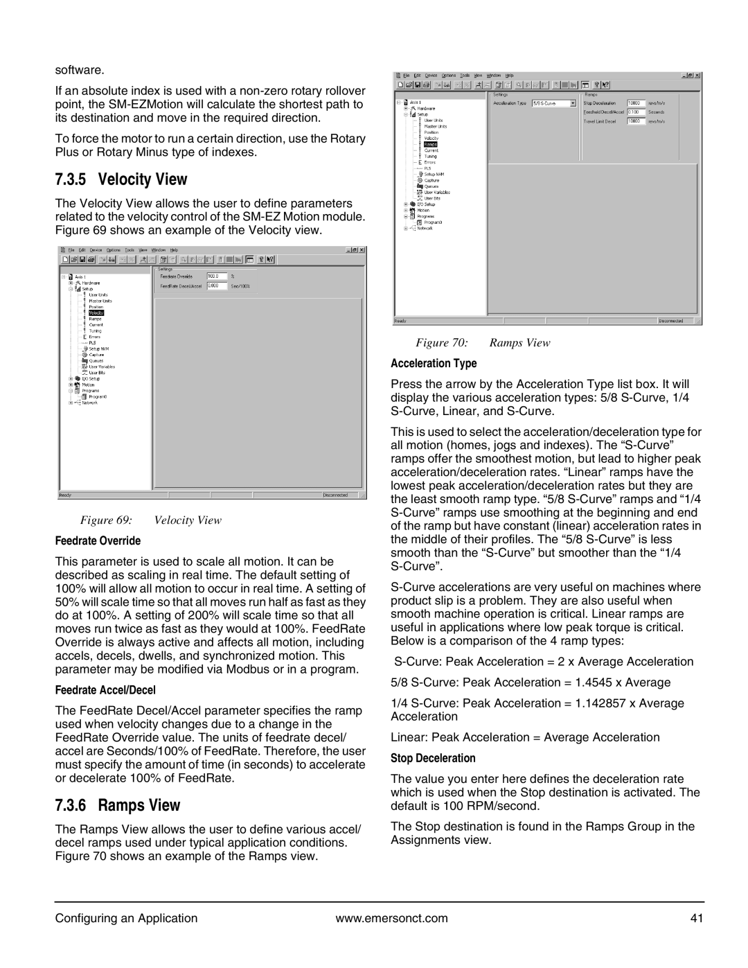
Figure 70: Ramps View
Acceleration Type
Press the arrow by the Acceleration Type list box. It will display the various acceleration types: 5/8
This is used to select the acceleration/deceleration type for all motion (homes, jogs and indexes). The
5/8
1/4
Linear: Peak Acceleration = Average Acceleration
Stop Deceleration
The value you enter here defines the deceleration rate which is used when the Stop destination is activated. The default is 100 RPM/second.
The Stop destination is found in the Ramps Group in the Assignments view.
Configuring an Application | www.emersonct.com | 41 |