Motor Definition Section
The motor definitions section contains the names and parameters of one or more user defined motors. The order of the parameters in the motor definition must match the example in Figure 120.
The motor parameters do not define with which drive(s) the motor may be used. Therefore, any motor in the .ddf file may be used with any drive.
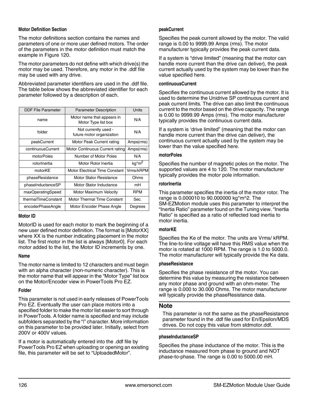
Abbreviated parameter identifiers are used in the .ddf file. The table below shows the abbreviated identifier for each parameter followed by a description of each.
DDF File Parameter | Parameter Description | Units | |
|
|
| |
name | Motor name that appears in | N/A | |
Motor Type list box | |||
|
| ||
|
|
| |
folder | Not currently used - | N/A | |
future motor organization | |||
|
| ||
|
|
| |
peakCurrent | Motor Peak Current rating | Amps(rms) | |
|
|
| |
continuousCurrent | Motor Continuous Current rating | Amps(rms) | |
|
|
| |
motorPoles | Number of Motor Poles | N/A | |
|
|
| |
rotorInertia | Motor Rotor Inertia | kg*m2 | |
motorKE | Motor Electrical Time Constant | Vrms/kRPM | |
|
|
| |
phaseResistance | Motor Stator Resistance | Ohms | |
|
|
| |
phaseInductanceSP | Motor Stator Inductance | mH | |
|
|
| |
maxOperatingSpeed | Motor Maximum Velocity | RPM | |
|
|
| |
thermalTimeConstant | Motor Thermal Time Constant | Sec. | |
|
|
| |
encoderPhaseAngle | Motor Encoder Phase Angle | Degrees | |
|
|
|
Motor ID
MotorID is used for each motor to mark the beginning of a new user defined motor definition. The format is [MotorXX] where XX is the number indicating placement in the motor list. The first motor in the list is always [Motor0]. For each motor added to the list, the Motor ID increments by one.
Name
The motor name is limited to 12 characters and must begin with an alpha character
Folder
This parameter is not used in early releases of PowerTools Pro EZ. Eventually the user can place motors into a specified folder to make the motor list easier to sort through in PowerTools. A folder name is specified and may include subfolders separated by the “” character. More information on this parameter to be provided later. Initially, select from 200V or 400V values.
If a motor is automatically entered into the .ddf file by PowerTools Pro EZ when uploading or opening an existing file, this parameter will be set to “UploadedMotor”.
peakCurrent
Specifies the peak current allowed by the motor. The valid range is 0.00 to 9999.99 Amps (rms). The motor manufacturer typically provides the peak current data.
If a system is “drive limited” (meaning that the motor can handle more current than the drive can deliver), the peak current actually used by the system may be lower than the value specified here.
continuousCurrent
Specifies the continuous current allowed by the motor. It is used to determine the Unidrive SP continuous current and peak current limits. The drive can also limit the continuous current to the motor based on the drive capacity. The range is 0.00 to 9999.99 Amps (rms). The motor manufacturer typically provides the continuous current data.
If a system is ‘drive limited” (meaning that the motor can handle more current than the drive can deliver), the continuous current actually used by the system may be lower than the value specified here.
motorPoles
Specifies the number of magnetic poles on the motor. The supported values are 4 to 120. The motor manufacturer typically provides the motor pole information.
rotorInertia
This parameter specifies the inertia of the motor rotor. The range is 0.000010 to 90.000000 kg*m^2. The
motorKE
Specifies the Ke of the motor. The units are Vrms/ kRPM. The
phaseResistance
Specifies the phase resistance of the motor. You can determine this value by measuring the resistance between any motor phase and ground with an
Note
This parameter is not the same as the phaseResistance parameter found in the .ddf file used for En/Epsilon/MDS drives. Do not copy this value from stdmotor.ddf.
phaseInductanceSP
Specifies the phase inductance of the motor. This is the inductance measured from phase to ground and NOT
126 | www.emersonct.com |
|