Codes, please refer to the Unidrive SP Users Guide or Unidrive SP Advanced Users Guide. Note that this trip code is not the same as the Trip Code or Error Code within a solutions module. For example, if an error occurs in a
Time Before Trip 0
All Trip Times for Trips other than Trip 0 are stored as a period of Time between Trip 0 and the specific Trip. The format for the Time is Hrs.Minutes. For example, if Trip 4 Time is shown as 1.20, that would signify that Trip 4 occurred 1 Hour and 20 Minutes prior to Trip 0. The largest value that can be stored in the Time Before Trip 0 is 600 Hours and 00 Minutes. If 600 Hours is exceeded, the 600 Hours and 00 Minutes is displayed in the Trip Log.
7.3.10 PLS View
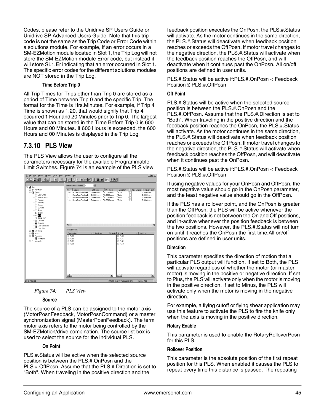
The PLS View allows the user to configure all the parameters necessary for the available Programmable Limit Switches. Figure 74 is an example of the PLS view.
Figure 74: | PLS View |
Source
The source of a PLS can be assigned to the motor axis (MotorPosnFeedback, MotorPosnCommand) or a master synchronization signal (MasterPosnFeedback). The term motor axis refers to the motor being controlled by the
On Point
PLS.#.Status will be active when the selected source position is between the PLS.#.OnPosn and the PLS.#.OffPosn. Assume that the PLS.#.Direction is set to "Both". When traveling in the positive direction and the
feedback position executes the OnPosn, the PLS.#.Status will activate. As the motor continues in the same direction, the PLS.#.Status will deactivate when feedback position reaches or exceeds the OffPosn. If motor travel changes to the negative direction, the PLS.#.Status will activate when the feedback position reaches the OffPosn, and will deactivate when it continues past the OnPosn. All on/off positions are defined in user units.
PLS.#.Status will be active if:PLS.#.OnPosn < Feedback Position £ PLS.#.OffPosn
Off Point
PLS.#.Status will be active when the selected source position is between the PLS.#.OnPosn and the PLS.#.OffPosn. Assume that the PLS.#.Direction is set to "Both". When traveling in the positive direction and the feedback position reaches the OnPosn, the PLS.#.Status will activate. As the motor continues in the same direction, the PLS.#.Status will deactivate when feedback position reaches or exceeds the OffPosn. If motor travel changes to the negative direction, the PLS.#.Status will activate when feedback position reaches the OffPosn, and will deactivate when it continues past the OnPosn.
PLS.#.Status will be active if:PLS.#.OnPosn < Feedback Position £ PLS.#.OffPosn
If using negative values for your OnPosn and OffPosn, the most negative value should go in the OnPosn parameter, and the least negative value should go in the OffPosn.
If the PLS has a rollover point, and the OnPosn is greater than the OffPosn, the PLS will be active whenever the position feedback is not between the On and Off positions, and
Direction
This parameter specifies the direction of motion that a particular PLS output will function. If set to Both, the PLS will activate regardless of whether the motor (or master motor) is moving in the positive or negative direction. If set to Plus, the PLS will activate only when the motor is moving in the positive direction. If set to Minus, the PLS will activate only when the motor is moving in the negative direction.
For example, a flying cutoff or flying shear application may use this feature to activate the PLS to fire the knife only when the axis is moving in the positive direction.
Rotary Enable
This parameter is used to enable the RotaryRolloverPosn for this PLS.
Rollover Position
This parameter is the absolute position of the first repeat position for this PLS. When enabled it causes the PLS to repeat every time this distance is passed. The repeating
Configuring an Application | www.emersonct.com | 45 |