7.3.4 Position View
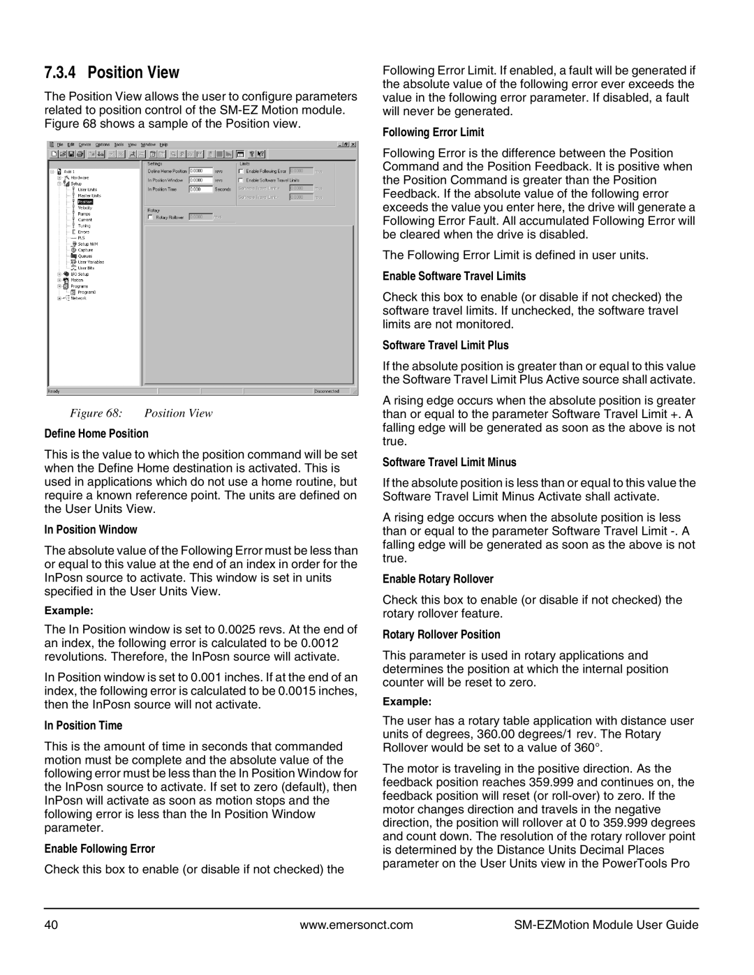
The Position View allows the user to configure parameters related to position control of the
Figure 68: | Position View |
Define Home Position
This is the value to which the position command will be set when the Define Home destination is activated. This is used in applications which do not use a home routine, but require a known reference point. The units are defined on the User Units View.
In Position Window
The absolute value of the Following Error must be less than or equal to this value at the end of an index in order for the InPosn source to activate. This window is set in units specified in the User Units View.
Example:
The In Position window is set to 0.0025 revs. At the end of an index, the following error is calculated to be 0.0012 revolutions. Therefore, the InPosn source will activate.
In Position window is set to 0.001 inches. If at the end of an index, the following error is calculated to be 0.0015 inches, then the InPosn source will not activate.
In Position Time
This is the amount of time in seconds that commanded motion must be complete and the absolute value of the following error must be less than the In Position Window for the InPosn source to activate. If set to zero (default), then InPosn will activate as soon as motion stops and the following error is less than the In Position Window parameter.
Enable Following Error
Check this box to enable (or disable if not checked) the
Following Error Limit. If enabled, a fault will be generated if the absolute value of the following error ever exceeds the value in the following error parameter. If disabled, a fault will never be generated.
Following Error Limit
Following Error is the difference between the Position Command and the Position Feedback. It is positive when the Position Command is greater than the Position Feedback. If the absolute value of the following error exceeds the value you enter here, the drive will generate a Following Error Fault. All accumulated Following Error will be cleared when the drive is disabled.
The Following Error Limit is defined in user units.
Enable Software Travel Limits
Check this box to enable (or disable if not checked) the software travel limits. If unchecked, the software travel limits are not monitored.
Software Travel Limit Plus
If the absolute position is greater than or equal to this value the Software Travel Limit Plus Active source shall activate.
A rising edge occurs when the absolute position is greater than or equal to the parameter Software Travel Limit +. A falling edge will be generated as soon as the above is not true.
Software Travel Limit Minus
If the absolute position is less than or equal to this value the Software Travel Limit Minus Activate shall activate.
A rising edge occurs when the absolute position is less than or equal to the parameter Software Travel Limit
Enable Rotary Rollover
Check this box to enable (or disable if not checked) the rotary rollover feature.
Rotary Rollover Position
This parameter is used in rotary applications and determines the position at which the internal position counter will be reset to zero.
Example:
The user has a rotary table application with distance user units of degrees, 360.00 degrees/1 rev. The Rotary Rollover would be set to a value of 360°.
The motor is traveling in the positive direction. As the feedback position reaches 359.999 and continues on, the feedback position will reset (or
40 | www.emersonct.com |
|