setting the bandwidth too high can result in ringing (audible ringing) in the velocity loop. The units for Velocity Loop Bandwidth are Hz.
Position Loop Response
The Position Loop Response directly impacts the stiffness of the position loop. Position Loop Response is effectively the Proportional gain term for the position loop controller. Higher Position Loop Response values will result in less following error throughout a motion profile, however setting the response too high can result in instability in the position loop.
Enable Velocity Feedforward
The Velocity Feedforward applies the calculated velocity command directly to the drive’s velocity loop. Enabling the Velocity Feedforward will generally yield faster velocity response, however the feedforward will introduce some overshoot. It is vital in applications that require the use of Jog profiles to enable the Velocity Feedforward signal.
Current Demand Filter
The Current Demand Filter is a
| 1 |
f = |
The units for the parameter are milliseconds. This parameter is written directly to parameter 4.12 of the Unidrive SP parameter database.
Simple Tuning Procedure
1.Select the desired Drive Type and Motor Type on the Drive/Encoder view in PowerTools Pro EZ.
2.Verify that the values of each of the motor parameters have been entered correctly, paying close attention to the Motor Rotor Inertia and the Motor Ke.
3.Enter the calculated Inertia Ratio into the edit box on the Tuning view.
4.Set the Position Loop Response to zero.
5.Enable the Velocity Feedforward parameter.
6.Configure an index that will simulate a step signal (make sure not to configure accel/decel values that you cause the motor to be current limited)
7.Initiate the index while recording velocity feedback on an oscilloscope.
8.Gradually increase the Velocity Loop Bandwidth until the velocity plot shows less than 20% velocity overshoot with no ringing (instability).
9.Audible noise may be introduced by increasing the Velocity Loop Bandwidth due to velocity jitter. The Current Demand Filter can be used to reduce the noise. Begin with a 1 ms value in the Current Demand Filter and gradually increase until the noise is reduced.
10.After adding the Current Demand Filter, you may be able to slightly increase the Velocity Loop Bandwidth again.
11.Gradually increase the Position Loop Response until Following Error is minimized. Often, a value approximately 1/4th of the Velocity Loop Bandwidth will work well. Increase until oscillation is introduced and then slightly decrease.
12.Save file.
7.3.9 Errors View
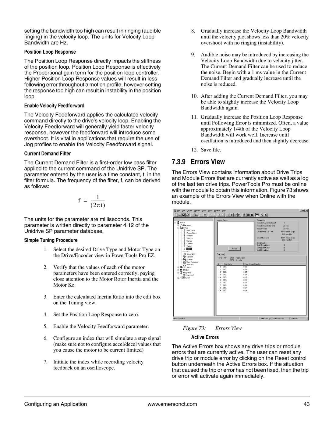
The Errors View contains information about Drive Trips and Module Errors that are currently active as well as a log of the last ten drive trips. PowerTools Pro must be online with the module to obtain this information. Figure 73 shows an example of the Errors View when Online with the module.
Figure 73: | Errors View |
Active Errors
The Active Errors box shows any drive trips or module errors that are currently active. The user can reset any drive trip or module error by clicking on the Reset control button underneath the Active Errors box. If the situation that caused the trip or error has not been fixed, then the trip or error will activate again immediately.
Configuring an Application | www.emersonct.com | 43 |