Feedhold Decel/Accel
When the Feedhold destination is activated, the motor will decelerate to a stop in the time specified by the FeedholdDecelTime parameter. When feedhold is cleared, the motor will accelerate back to speed in the same specified period of time.
Feedhold is a means to halt the motor within a velocity profile and then return to the profile later at the exact same place in the profile. Feedhold does not ramp and does not decelerate in terms of velocity. Instead, it stops by decelerating time. For example, if the motor is running at 50 revs/second and feedhold is activated with 2 seconds specified in the FeedholdDecelTime parameter, then the motor will actually slow and stop in 2 seconds as measured time (on a time/velocity profile) goes from 100% to 0%.
Travel Limit Deceleration
The value entered here is the deceleration ramp that is used when a software or hardware travel limit is hit.
7.3.7 Current View
The Current View allows the user to configure Current Level Flags and Current Limits for use in the application.
Figure 71: Torque View
Current Level
This parameter sets the activation point for the Current Level Active source. If set to 100%, the Current Level Active source will activate any time the Current Command reaches or exceeds 100% continuous.
Current Limit
This parameter sets the value to which the Current Command will be limited when the Current Limit Enable destination is active. To make the Current Limit always active, assign the Current Limit Enable destination to the Initially Active source on the Assignments view.
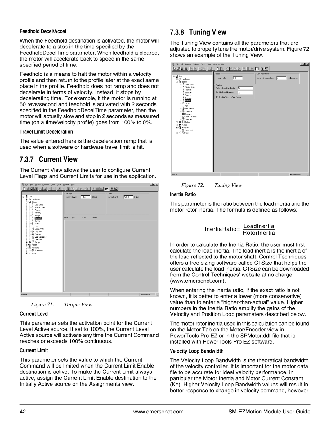
7.3.8 Tuning View
The Tuning View contains all the parameters that are adjusted to properly tune the motor/drive system. Figure 72 shows an example of the Tuning View.
Figure 72: | Tuning View |
Inertia Ratio
This parameter is the ratio between the load inertia and the motor rotor inertia. The formula is defined as follows:
LoadInertia
InertiaRatio=
RotorInertia
In order to calculate the Inertia Ratio, the user must first calculate the load inertia. The load inertia is the inertia of the load reflected to the motor shaft. Control Techniques offers a free sizing software called CTSize that helps the user calculate the load inertia. CTSize can be downloaded from the Control Techniques’ website at no charge (www.emersonct.com).
When entering the inertia ratio, if the exact ratio is not known, it is better to enter a lower (more conservative) value than to enter a
The motor rotor inertia used in this calculation can be found on the Motor Tab on the Motor/Encoder view in PowerTools Pro EZ or in the SPMotor.ddf file that is installed with PowerTools Pro EZ software.
Velocity Loop Bandwidth
The Velocity Loop Bandwidth is the theoretical bandwidth of the velocity controller. It is important for the motor data file to be accurate for ideal velocity performance, in particular the Motor Inertia and Motor Current Constant (Ke). Higher Velocity Loop Bandwidth values will result in better response to change in velocity command, however
42 | www.emersonct.com |
|