Error Code | Cause | Error | Possible Reason | Possible Solution | |
(x.50) | Trip? | ||||
|
|
| |||
|
|
|
|
| |
|
|
|
| Switch module located in Slot 2 to match | |
|
|
| Option module selected for Slot 2 in | module type selected in PowerTools Pro | |
|
|
| file. Alternatively, update the PowerTools | ||
172 | Y | Invalid Slot 2 Selection | PowerTools Pro file does not match | ||
Pro configuration to match the module | |||||
|
|
| actual module type fitted | ||
|
|
| type actually fitted, and then | ||
|
|
|
| ||
|
|
|
| the configuration. | |
|
|
|
|
| |
|
|
|
| Switch module located in Slot 3 to match | |
|
|
| Option module selected for Slot 3 in | module type selected in PowerTools Pro | |
|
|
| file. Alternatively, update the PowerTools | ||
173 | Y | Invalid Slot 3 Selection | PowerTools Pro file does not match | ||
Pro configuration to match the module | |||||
|
|
| actual module type fitted | ||
|
|
| type actually fitted, and then | ||
|
|
|
| ||
|
|
|
| the configuration. | |
|
|
|
|
| |
174 | Y | File Corruption Error - Consult Factory |
|
| |
|
|
|
|
| |
|
|
| Modify circuitry of devices connected to | ||
|
|
| 20mA maximum total output current. If | ||
|
|
| the | ||
175 | Y | Module Output Overload | this fault occurs, the digital output | ||
so that they draw no more than 20mA | |||||
|
|
| device attached to the module outputs | ||
|
|
| total. | ||
|
|
| is drawing too much current. | ||
|
|
|
| ||
|
|
|
|
|
13.2 Analog Outputs
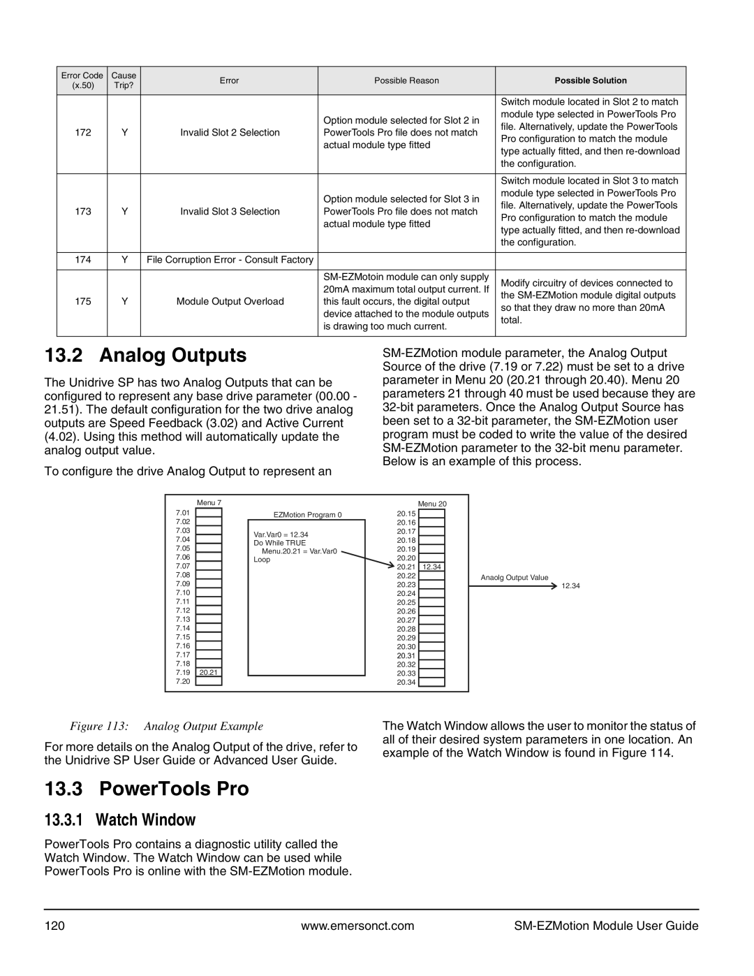
The Unidrive SP has two Analog Outputs that can be configured to represent any base drive parameter (00.00 - 21.51). The default configuration for the two drive analog outputs are Speed Feedback (3.02) and Active Current (4.02). Using this method will automatically update the analog output value.
To configure the drive Analog Output to represent an
| Menu 7 |
7.01 | EZMotion Program 0 |
7.02 |
|
|
7.03 |
| Var.Var0 = 12.34 |
7.04 |
| |
| Do While TRUE | |
7.05 |
| |
| Menu.20.21 = Var.Var0 | |
|
|
7.06Loop
7.08
7.09
7.10
7.11
7.12
7.13
7.14
7.15
7.16
7.17
7.18
7.1920.21
Menu 20
20.15
20.16
20.17
20.18
20.19
20.20 ![]() 20.21 12.34
20.21 12.34
20.22Anaolg Output Value
20.23![]() 12.34
12.34
20.24
20.25
20.26
20.27
20.28
20.29
20.30
20.32
20.33
20.34
Figure 113: Analog Output Example
For more details on the Analog Output of the drive, refer to the Unidrive SP User Guide or Advanced User Guide.
The Watch Window allows the user to monitor the status of all of their desired system parameters in one location. An example of the Watch Window is found in Figure 114.
13.3 PowerTools Pro
13.3.1 Watch Window
PowerTools Pro contains a diagnostic utility called the Watch Window. The Watch Window can be used while PowerTools Pro is online with the
120 | www.emersonct.com |
|