Distance
Units Name
This is a
Decimal Places
The number of decimal places set in this parameter determines the number of digits after the decimal point used in all distance and position parameters throughout the software. Using a high number of decimal places will improve position resolution, but will also limit the range of absolute position. You can select from zero to six decimal places of accuracy.
Scaling
A Characteristic Distance and Length must be established to allow the module to scale user units back to actual motor revolutions. This scaling factor is as follows:
Characteristic Distance
Scaling =
Characteristic Length
Scaling - Characteristic Distance
This is the distance the load travels (in user units) when the motor travels the characteristic length (in motor revolutions).
Scaling - Characteristic Length
This is the distance the motor travels (in whole number of revolutions) to achieve one characteristic distance of load travel.
Velocity
Time Scale List Box
The time can be one of two values: seconds or minutes. This selection sets the
Acceleration
Time Scale List Box
From this list box, select the acceleration time scale to be used for all
7.3.3 Master Units Setup View
The Master Units Setup view is used to configure the parameters for the master axis used in synchronized motion applications. The master axis is most often a second encoder, or possibly another upstream drive.
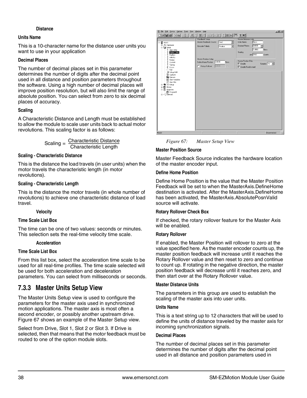
Figure 67 shows an example of the Master Setup view.
Select from Drive, Slot 1, Slot 2 or Slot 3. If Drive is selected, then that means that the motor feedback must be routed to one of the option module slots.
Figure 67: Master Setup View
Master Position Source
Master Feedback Source indicates the hardware location of the master encoder input.
Define Home Position
Define Home Position is the value that the Master Position Feedback will be set to when the MasterAxis.DefineHome destination is activated. After the MasterAxis.DefineHome has been activated, the MasterAxis.AbsolutePosnValid source will activate.
Rotary Rollover Check Box
If checked, the rotary rollover feature for the Master Axis will be enabled.
Rotary Rollover
If enabled, the Master Position will rollover to zero at the value specified here. As the master encoder counts up, the master position feedback will increase until it reaches the Rotary Rollover value and then reset to zero and continue to count up. If rotating in the negative direction, the master position feedback will decrease until it reaches zero, and then start over at the Rotary Rollover value.
Master Distance Units
The parameters in this group are used to establish the scaling of the master axis into user units.
Units Name
This is a text string up to 12 characters that will be used to define the units of distance traveled by the master axis for incoming synchronization signals.
Decimal Places
The number of decimal places set in this parameter determines the number of digits after the decimal point used in all distance and position parameters used in
38 | www.emersonct.com |
|