Installation
This sections details the installation of the JMP 9600, including:
•Mounting the Media Player
•Connections and Features
Mounting the Media Player
![]() CAUTION: Installation and service must be performed by authorized personnel only.
CAUTION: Installation and service must be performed by authorized personnel only.
Detailed mounting instructions can be found in the “Mounting and Maintenance“ section. The 2U high, JMP 9600 can be placed on a tabletop or mounted on a rack shelf. Use the included hardware for rack mounting.
Connections and Features
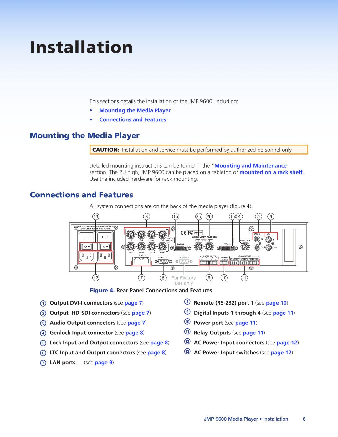
All system connections are on the back of the media player (figure 4).
13 |
| 3 |
|
| 1a | 2b | 2b |
| 1b | 4 |
| 5 |
| 6 | |||
INPUT: |
|
|
|
|
|
|
|
|
|
|
|
|
|
|
|
|
|
USE ONLY: F2 AH 240V FUSES. |
|
|
|
|
|
|
|
|
|
|
|
|
|
|
|
|
|
|
|
|
|
|
| JMP 9600 |
|
|
|
|
|
|
| LOCK |
| LTC | |
|
|
|
|
|
|
|
|
|
|
|
|
|
|
|
| ||
|
|
|
| DIGITAL | DIGITAL VIDEO OUTPUTS |
|
|
|
|
|
| IN |
| ||||
| 1 HDSDI |
|
|
|
|
|
|
| IN | ||||||||
AUDIO |
| 2 |
|
|
| GENLOCK | |||||||||||
|
|
|
|
| |||||||||||||
|
|
|
| OUT |
|
|
|
|
|
|
|
|
|
| |||
|
|
|
|
|
|
|
|
|
|
|
|
|
|
| |||
|
|
|
|
|
|
|
|
|
|
|
|
|
|
|
| OUT | OUT |
|
|
|
|
|
|
|
|
|
|
|
|
|
| ||||
1 | LAN | 2 | REMOTE 1 |
| REMOTE 2 |
| DIGITAL INPUTS |
|
| RELAY OUTPUTS |
|
| |||||
|
|
|
| +1- +2- | +3- +4- | POWER | R1 |
| R2 | R3 | R4 |
|
| ||||
|
|
|
|
|
|
|
|
|
| 12V | NC C NO NC | C NO NC C | NO NC C NO |
|
| ||
12 | 7 |
| 8 |
| For Factory |
|
| 9 | 10 |
|
|
| 11 |
|
|
| |
|
|
|
|
|
| Use only |
|
|
|
|
|
|
|
|
|
|
|
Figure 4. Rear Panel Connections and Features
AOutput DVI-I connectors (see page 7)
BOutput HD-SDI connectors (see page 7)
CAudio Output connectors (see page 7)
DGenlock Input connector (see page 8)
ELock Input and Output connectors (see page 8)
FLTC Input and Output connectors (see page 8)
GLAN ports — (see page 9)
HRemote (RS-232) port 1 (see page 10)
IDigital Inputs 1 through 4 (see page 11)
JPower port (see page 11)
KRelay Outputs (see page 11)
LAC Power Input connectors (see page 12)
MAC Power Input switches (see page 12)
JMP 9600 Media Player • Installation | 6 |