High Frame Rate
The high frame rate mode supports resolutions of 1920x1080 and 2048x1080 at 48, 50, and 60Hz by using the dual
The Extron JPEG 2000 Encoder software (see “Encoding Guidelines”) automatically generates the file format required for high frame rate operation when you select the corresponding resolution and frame rate.
The high frame rate mode requires that the connected display support the SMPTE
372M
![]() NOTE: The Extron USP 507 supports only
NOTE: The Extron USP 507 supports only ![]() are limited to 50 Hz and 60 Hz (48 Hz is not supported).
are limited to 50 Hz and 60 Hz (48 Hz is not supported).
Using Digital Inputs and Relays
![]() WARNING: 12 VDC is always present on the inputs and relays Power port when the
WARNING: 12 VDC is always present on the inputs and relays Power port when the ![]() media player is powered on. Ensure that no conductive material comes into
media player is powered on. Ensure that no conductive material comes into
contact with these terminals.
DIGITAL INPUTS |
|
|
|
| RELAY OUTPUTS | |||||||
+1- +2- | +3- +4- |
| POWER |
| R1 |
| R2 | R3 | R4 | |||
|
|
|
| 12V |
| NC C NO NC |
| C NO NC C | NO NC C NO | |||
|
|
|
|
|
|
|
|
|
|
|
|
|
INPUT: |
|
|
|
|
|
|
|
|
|
|
|
|
|
|
|
|
|
USE ONLY: F2 AH 240V FUSES. |
|
|
|
|
|
|
|
|
|
|
|
|
|
|
|
|
|
|
|
|
|
|
| JMP 9600 |
|
|
|
|
|
|
|
| LOCK | LTC | |
|
|
|
|
|
|
|
|
|
|
|
|
|
|
|
| ||
|
|
|
| DIGITAL |
| DIGITAL VIDEO OUTPUTS |
|
|
|
|
| IN |
| ||||
|
| HDSDI |
|
|
|
|
|
|
| IN | |||||||
AUDIO |
| 1 | 2 |
|
|
| GENLOCK | ||||||||||
|
|
|
| OUT |
|
|
|
|
|
|
|
|
|
|
| ||
|
|
|
|
|
|
|
|
|
|
|
|
|
|
|
| ||
|
|
|
|
|
|
|
|
|
|
|
|
|
|
|
| OUT | OUT |
|
|
|
|
|
|
|
|
|
|
|
|
|
| ||||
1 | LAN | 2 | REMOTE 1 | REMOTE 2 |
| DIGITAL INPUTS |
| RELAY OUTPUTS |
|
| |||||||
|
|
|
| 1 | 2 | 3 | 4 | POWER | R1 | R2 | R3 |
| R4 |
| |||
|
|
|
|
|
|
| + - | + - | + - | + - | 12V | NC C NO NC | C NO NC C | NO NC C NO |
| ||
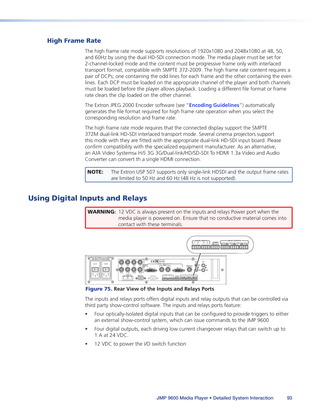
Figure 75. Rear View of the Inputs and Relays Ports
The inputs and relays ports offers digital inputs and relay outputs that can be controlled via third party
•Four
•Four digital outputs, each driving low current changeover relays that can switch up to
1 A at 24 VDC.
•12 VDC to power the I/O switch function
JMP 9600 Media Player • Detailed System Interaction | 93 |