Optically-isolated Digital Inputs
The digital input connections are implemented as four + and – terminals on 3.5 mm captive screw terminal blocks. Because each input is
![]() NOTE: By factory default, status notification for Digital Inputs 1 through 4 is disabled.
NOTE: By factory default, status notification for Digital Inputs 1 through 4 is disabled.
To be made operational, they must be enabled using the Set input trigger
on MSVPP command (see “Applicable MSVPP Commands”).
The
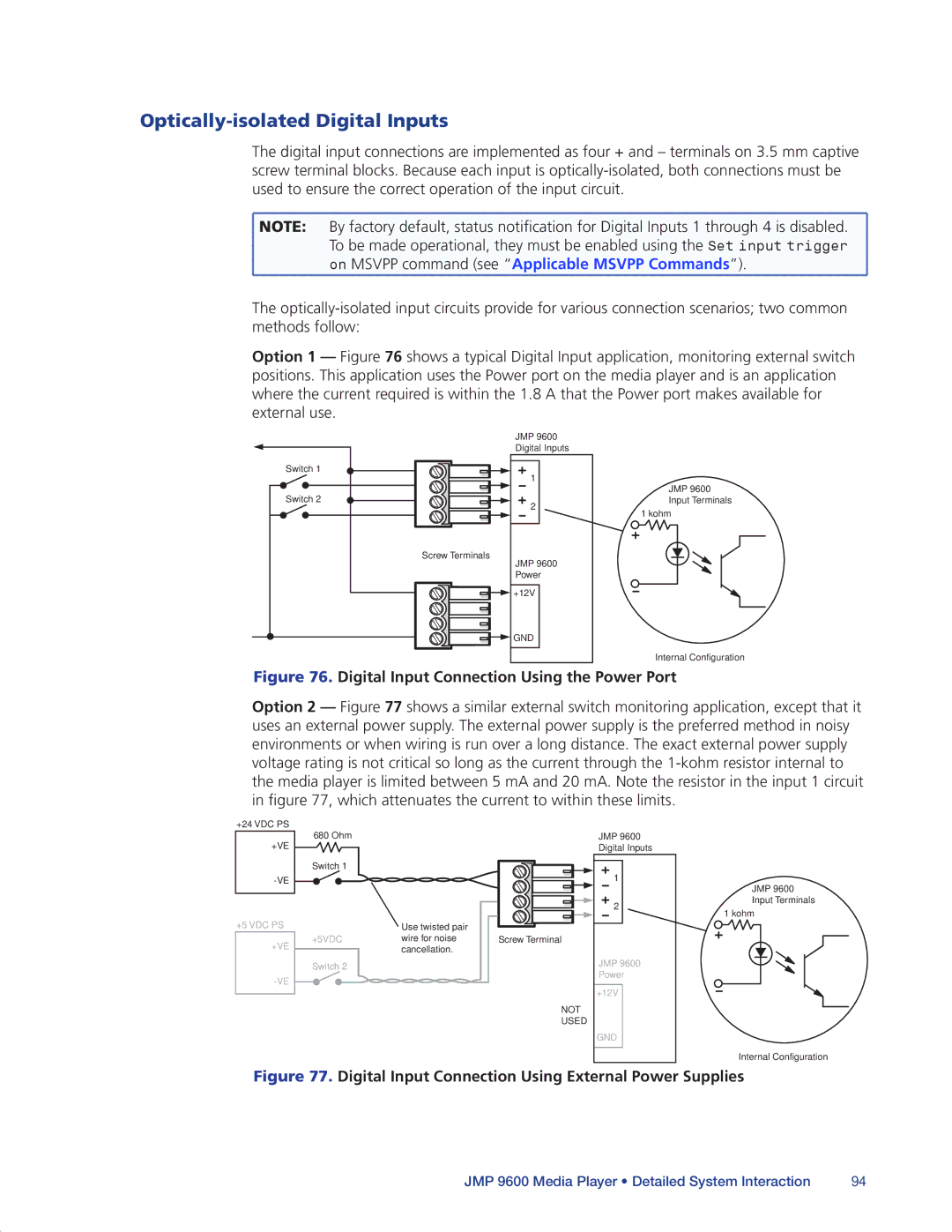
Option 1 — Figure 76 shows a typical Digital Input application, monitoring external switch positions. This application uses the Power port on the media player and is an application where the current required is within the 1.8 A that the Power port makes available for external use.
Switch 1
Switch 2
Screw Terminals
JMP 9600 Digital Inputs
1
2
JMP 9600 Power
JMP 9600 Input Terminals
1 kohm
![]()
![]()
![]()
![]()
![]() +12V
+12V
![]()
![]()
![]()
![]()
![]()
![]() GND
GND
Internal Configuration
Figure 76. Digital Input Connection Using the Power Port
Option 2 — Figure 77 shows a similar external switch monitoring application, except that it uses an external power supply. The external power supply is the preferred method in noisy environments or when wiring is run over a long distance. The exact external power supply voltage rating is not critical so long as the current through the
+24 VDC PS +VE
+5 VDC PS
+VE
680 Ohm
Switch 1
| Use twisted pair |
|
|
|
|
|
|
| |
|
|
|
| |
|
|
|
| |
+5VDC | wire for noise | Screw Terminal |
| |
| cancellation. |
|
|
|
Switch 2 |
|
|
|
|
NOT
USED
JMP 9600 Digital Inputs
1
2
JMP 9600 Power
+12V
GND
JMP 9600 Input Terminals
1 kohm
Internal Configuration
Figure 77. Digital Input Connection Using External Power Supplies
JMP 9600 Media Player • Detailed System Interaction | 94 |