Digital Inputs and Relays
The Digital Inputs and Relays ports provides
![]() NOTES: • By factory default, automatic reporting of Digital Inputs 1 through 4 is
NOTES: • By factory default, automatic reporting of Digital Inputs 1 through 4 is
disabled. To enable reporting, use the Set input trigger on MSVPP command (see the “Programming Guide” section).
• Use a single cable for all inputs and relay ports and snap one of the included ferrite beads on the cable, as close to the unit as possible.
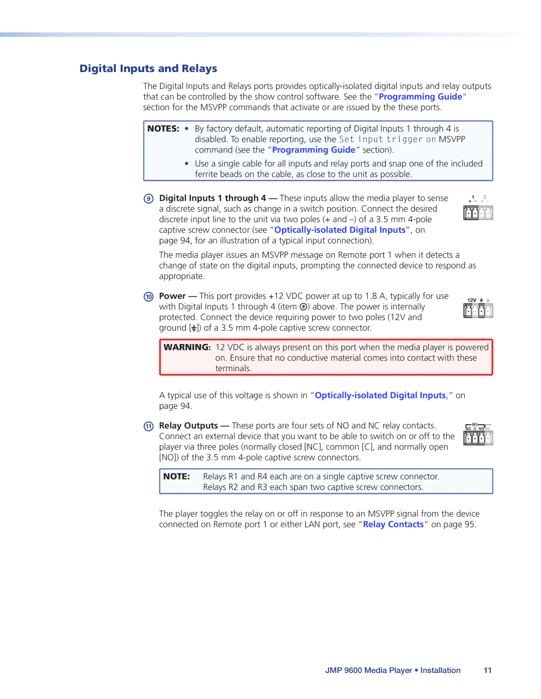
IDigital Inputs 1 through 4 — These inputs allow the media player to sense a discrete signal, such as change in a switch position. Connect the desired discrete input line to the unit via two poles (+ and
+1- +2 -
The media player issues an MSVPP message on Remote port 1 when it detects a change of state on the digital inputs, prompting the connected device to respond as appropriate.
J Power — This port provides +12 VDC power at up to 1.8 A, typically for use
with Digital Inputs 1 through 4 (item I) above. The power is internally protected. Connect the device requiring power to two poles (12V and ground [![]() ]) of a 3.5 mm
]) of a 3.5 mm
12V
![]() WARNING: 12 VDC is always present on this port when the media player is powered
WARNING: 12 VDC is always present on this port when the media player is powered ![]()
![]() on. Ensure that no conductive material comes into contact with these
on. Ensure that no conductive material comes into contact with these ![]()
terminals.
A typical use of this voltage is shown in
K Relay Outputs — These ports are four sets of NO and NC relay contacts. | NC C NO NC |
| R1 |
Connect an external device that you want to be able to switch on or off to the |
|
player via three poles (normally closed [NC], common [C], and normally open |
|
[NO]) of the 3.5 mm |
|
NOTE: Relays R1 and R4 each are on a single captive screw connector. |
|
Relays R2 and R3 each span two captive screw connectors. |
|
The player toggles the relay on or off in response to an MSVPP signal from the device connected on Remote port 1 or either LAN port, see “Relay Contacts“ on page 95.
JMP 9600 Media Player • Installation | 11 |
