Connections for Synchronized Multi-player Operation
The following equipment is required for an example of a small synchronized system:
•Two JMP 9600 Media Players (see figure 67, below)
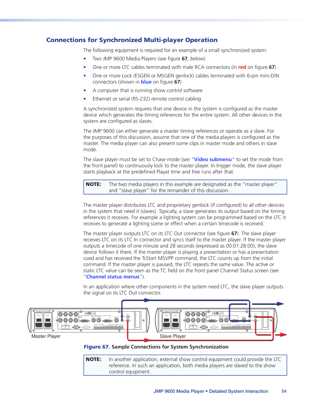
•One or more LTC cables terminated with male RCA connectors (in red on figure 67)
•One or more Lock (ESGEN or MSGEN genlock) cables terminated with
•A computer that is running show control software
•Ethernet or serial
A synchronized system requires that one device in the system is configured as the master device which generates the timing references for the entire system. All other devices in the system are configured as slaves.
The JMP 9600 can either generate a master timing references or operate as a slave. For the purposes of this discussion, assume that one of the media players is configured as the master. The media player can also present some clips in master mode and others in slave mode.
The slave player must be set to Chase mode (see “Video submenu“ to set the mode from the front panel) to continuously lock to the master player. In trigger mode, the slave player starts playback at the predefined Playat time and free runs after that.
![]() NOTE: The two media players in this example are designated as the “master player”
NOTE: The two media players in this example are designated as the “master player” ![]() and “slave player” for the remainder of this discussion.
and “slave player” for the remainder of this discussion.
The master player distributes LTC and proprietary genlock (if configured) to all other devices in the system that need it (slaves). Typically, a slave generates its output based on the timing references it receives. For example a lighting system can be programmed based on the LTC it receives to generate a lighting scene or effect when a certain timecode is received.
The master player outputs LTC on its LTC Out connector (see figure 67). The slave player receives LTC on its LTC In connector and syncs itself to the master player. If the master player outputs a timecode of one minute and 28 seconds (expressed as 00:01:28:00), the slave device follows it there. If the master player is playing a presentation or has a presentation cued and has received the TcStart MSVPP command, the LTC counts up from the initial command. If the master player is paused, the LTC repeats the same value. The active or static LTC value can be seen as the TC field on the front panel Channel Status screen (see “Channel status menus”).
In an application where other components in the system need LTC, the slave player outputs the signal on its LTC Out connector.
INPUT:I : |
|
|
|
|
|
|
|
|
|
|
|
|
|
|
|
|
| INPUT:I : |
|
|
|
|
|
|
|
|
|
|
|
|
|
|
|
|
|
USE ONLY:: F2 AH 240V FUSES.. |
|
|
|
|
|
|
|
|
|
|
|
|
|
|
|
|
| USE ONLY:: F2 AH 240V FUSES.. |
|
|
|
|
|
|
|
|
|
|
|
|
|
|
|
|
|
|
|
|
|
|
| JMP 9600 |
|
|
|
|
|
|
|
| LOCK | LTC |
|
|
|
|
|
| JMP 9600 |
|
|
|
|
|
|
|
| LOCK | LTC | ||
|
|
|
|
|
|
|
|
|
|
|
|
|
|
|
|
|
|
|
|
|
|
|
|
|
|
|
|
|
|
|
| ||||
|
|
|
| DIGITAL |
| DIGITAL VIDEO OUTPUTS |
|
|
|
|
| IN |
|
|
|
|
| DIGITAL |
| DIGITAL VIDEO OUTPUTS |
|
|
|
|
| IN |
| ||||||||
AUDIO |
| 1 | HDSDI | 2 |
|
|
| GENLOCK | IN | AUDIO |
| 1 | HDSDI | 2 |
|
|
| GENLOCK | IN | ||||||||||||||||
|
|
|
| OUT |
|
|
|
|
|
|
|
|
|
|
|
|
|
|
| OUT |
|
|
|
|
|
|
|
|
|
|
| ||||
|
|
|
|
|
|
|
|
|
|
|
|
|
|
|
|
|
|
|
|
|
|
|
|
|
|
|
|
|
|
|
| ||||
|
|
|
|
|
|
|
|
|
|
|
|
|
|
|
| OUT | OUT |
|
|
|
|
|
|
|
|
|
|
|
|
|
|
|
| OUT | OUT |
|
|
|
|
|
|
|
|
|
|
|
|
|
|
|
|
|
|
|
|
|
|
|
|
|
|
|
| ||||||||
1 | LAN | 2 | REMOTE 1 | REMOTE 2 |
| DIGITAL INPUTS |
| RELAY OUTPUTS |
|
| 1 | LAN | 2 | REMOTE 1 | REMOTE 2 |
| DIGITAL INPUTS |
| RELAY OUTPUTS |
|
| ||||||||||||||
|
|
|
| 1 | 2 | 3 | 4 | POWER | R1 | R2 | R3 |
| R4 |
|
|
|
|
| 1 | 2 | 3 | 4 | POWER | R1 | R2 | R3 |
| R4 |
| ||||||
|
|
|
|
|
|
| + - | + - | + - | + - | 12V | NC C NO NC | C NO NC C | NO NC C NO |
|
|
|
|
|
|
|
| + - | + - | + - | + - | 12V | NC C NO NC | C NO NC C | NO NC C NO |
| ||||
Master Player | Slave Player |
Figure 67. Sample Connections for System Synchronization | |
NOTE: | In another application, external show control equipment could provide the LTC |
| reference. In such an application, both media players are slaved to the show |
| control equipment. |
JMP 9600 Media Player • Detailed System Interaction | 84 |