DesignJet 1050C/1055CM
Large-Format Printers
Safety Symbols
DesignJet 1050C/1055CM
Readership Part Numbers
Using this Manual
Purpose
Conventions
Table of Contents
System Error Codes
Service Tests and Utilities
Print Quality
Parts and Diagrams
Preventive Maintenance
Glossary Index
Table of Contents
Troubleshooting1
When reporting the System Error Code, make sure that you
Guide to Troubleshooting the Printer
Troubleshooting System Error Codes
Introduction
Performing the Necessary Service Calibrations
Performing a Service Test on a Failed Assembly
Solving Image Quality Problems
Troubleshooting
Printer does not Power on
ALL the Front-Panel LEDs are Lit but Nothing Else Happens
Printer Continuously Rejects Printheads
Line Sensor has Problems Detecting Media
Cover Sensors are not Working
Troubleshooting Media Jams/Printhead Crashes
Troubleshooting Shutdowns
Attempting any procedures to resolve the problem
Problem as explained as follows
Each case, make sure that you power OFF the printer before
Printhead Cleaner Path
Vacuum suction much lower at high altitudes
Problems with the Vacuum Fan
Bin marks on prints done on HP High Gloss media
Troubleshooting
HP-GL/2 color differences in different HP DesignJet Printers
Banding at variable extreme environmental conditions
Banding due to Ink Cartridge replacement while printing
Long term bleed and hue shift on HP High Gloss media
Rice Paper not supported
Media is causing the problem and not the Printer. Do not
Cut Sheet rice paper loading failure
Front Panel Keeps Indicating that Media Is Misaligned or
Solving Media-Handling Problems
Media may be loaded at an angle, causing the media to be
Incorrectly Positioned
Panel Menu
HP DesignJets 1050C
Image Quality
On, Off 7586, HP-GL/2
Utilities
How to Print the Service Configuration Print
Service Configuration Print
Press Enter
How to Use the Service Configuration Print
Sample of the Service Configuration Print
Troubleshooting
System Error Codes
System Error Codes
Continuable and Non-Continuable Error Codes
01002D Non-Continuable
Non-Continuable
Try the following
Calibrations Backup
Memory Dram Dimm Test failure
Make sure that you select Electronics Module Replaced when
010040
010042
ProblemError in Paper-axis Motor Encoder
EIO Accessories EIO Card/Hard Disk Drive Error
04Cxxx
One of the Printheads has an Internal Electrical Problem
060301
Problem with setting the Voltage of the Printheads
060309
06030B
09xxxx Non-Continuable
0A0000
Air Pressure is below the minimum requirement
0A0020
Error in Calibrating the APS Sensor
Problem in Depressurizing Air System
0A0030
0A0050 Non-Continuable
0A0070 Continuable
ProblemDrop Detector not Calibrated for all Printheads
System Error Codes During Initialization
0B0004
Unable to detect Pump
0B0007
Unable to detect Vacuum Fan
0B0009
Unable to detect Aerosol Fan Included on the Right Cover
0B000B
Pump or Pressure Sensor not working
HP No.80 Ink Supplies Troubleshooting
What are HP No.80 Supplies?
Printheads and Printhead Cleaners
Ink Cartridges
Identifying the Components
General Information About HP No.80 Supplies
Some General Precautions When Handling HP No.80 Supplies
Priming the Ink System
When Should You Replace the HP No.80 Supplies?
Show the Wrong Model message
Front Panel Display
Printing Monitor Quality
Obtaining Ink Cartridge Information
Ready
Obtaining Printhead Information
Cyan printhead info HP No.80 printhead
Ink Cartridge Status Messages
Ink Cartridge Status While Printing
Ink Cartridge Status While Replacing
Main actions for all 4 status messages is as follows
Printhead Status Messages While Printing
Refer to page 3-9,Obtaining Printhead Information
Carriage Assembly is faulty
Front panel displays Ready/Replace Draft Normal Best
Insert, it is possible that the Carriage Assembly is faulty
Printhead Status Messages While Replacing
Genuine HP No.80 Printhead
Carriage during the priming process, they will be rejected
Summary of Solving HP No.80 Supplies Problems
Front panel will show the Wrong Model message
Carriage Interconnect Wiper
This can damage the printhead and reduce print quality
Service Tests Utilities
Introduction
Diagnostics Self Test
Initialization Sequences
Must power OFF the Printer and Power on again before
Service Tests Diagnostics
Service Tests work in a special Mode which does not
Trying to print
Order to enter the Service Utility Menu, please refer to
Entering the Service Tests Menu
Instructions on
Electronic Systems
Make Selection
Electronics Failure
Dram Test Failure
You will be able to determine exactly which component failed
Carriage Test Failure
EIO Card
If this Test PASSES, do not Replace the EIO Card
Hard Disk Drive
Following message will appear on the front panel
Service Tests and Utilities
Check that the Hard Disk Drive is actually installed before
Test will of course always fail
Ink Pressure System
Tubes System Failure
APS Test Failure
Service Tests and Utilities Appear on the front panel
Scan Axis
Perform this test with the Printheads and the Tubes System
Max. PWM
Service Tests and Utilities
Paper Axis
Make sure you perform this test with no media loaded
Max PWM Avg PWM Max PWM C Avg PWM C
Drop Detector
Following step, make sure you do not drop the piece
Paper inside the Drop Detector
If this Test PASSES, do not Replace the Drop
Service Utilities
Entering the Service Utilities Menu
Enter Service Utilities again
Make sure that there is enough ink remaining in the Ink
New Tubes System has been installed
Tubes Purge
Enough ink remaining, you will get a warning message
Printer will then begin to purge the tubes system
Lift window to replace Setup printheads
Backup the Eerom Data from the Electronics Module. Make
Perform the Calibrations Backup ⇒ Page 5-19 in order to
Sure you select Tubes Replaced when performing
Release Info
Set Asian PS Fonts
Cancel
System and the Electronics Module have been replaced at
Printer Model Type
Same time
Printer model type selection done
Overdrive Cleaning
Roller and Roller Mark in order to clean them
Eerom Utilities
If you want to Test the Eerom
Displayed on the front panel
If you want to Clear the Eerom
Once the Eerom has been cleared, the following message will
Be displayed on the front panel
Facility on or OFF
Printhead Check
Make Selection
Default Baudrate for serial communication is
Mon. Mode Baud Sel
Change Baudrate
Service Calibrations
Service Calibrations
Refer to the following page for the relevant Calibration
Service Calibrations
This Calibration is no Longer Required
Entering the Service Calibrations Menu
You will not be able to access the Service Tools submenu
Service Calibrations
Accuracy Calibration
Media apart from HP High Gloss Photo Paper
Do not use any other type of media apart from HP High Gloss
Photo Paper
Measuring
Make sure you load HP Coated media in to the Printer before
Line Sensor
Performing this calibration
Calibrating line sensor Please wait
Service Station
Apart from HP Coated or HP High Gloss Photo Paper
Press Enter to continue
Roller Mark Position
Make sure that you unload the media from the Printer before
Roller mark position calibrated Press Enter to continue
Service Calibrations
Pen to Paper Spacing
Use any other type of media apart from HP Coated or HP High
Color to Color calibration
Make sure that you load E/A0 size HP High Gloss Photo Paper
Gloss Photo Paper
From HP Coated or HP High Gloss Photo Paper
Make sure that you press Form Feed and Cut when you have
Media roll
If the calibration pattern is bad
Calibrations Backup
If the Electronics Module was replaced
If the Tubes System was replaced
Tubes System Has been replaced?
Make sure you load media before performing this calibration
Pen Alignment
Do not use Clear Film, Vellum or Natural Tracing Paper
Do not use Clear Film, Vellum or Natural Tracing Paper
Carriage Height Calibration
Procedure should be carried out using the Carriage Height
Assembly or Center Platen Assembly
Tool See below that came with the new Carriage
Assembly has to be moved along the length of the printer for
With the carriage itself See below
Service Calibrations
Service Calibrations
Service Calibrations
Service Calibrations
Service Calibrations
Service Calibrations
Service Calibrations
Print Quality
Print Quality Troubleshooting Checklist
Print Quality
Photo Paper when performing the Accuracy Calibration
Print Modes
Considerations for Printing the Print Quality Test
How to Use the Print Quality Test
What is the Print Quality Test?
Printing the Print Quality Test
Utilities Test Prints
Nozzle Print Test
Print Quality
How to fix the Nozzle Defects
Color Alignment Print Test
Affects mostly Normal and Draft modes
Solving the Color Alignment Problem
Overall Print Quality Test in Best mode
What is Banding?
Solving the Banding Problem
Test pattern in all the primary and secondary color columns
Service Accuracy Calibration
Aligning the Printheads
Troubleshooting Print Quality Problems
Problems with Stepped Lines
Problems with printing lines
Problems with Color-to-Color Alignment
Print Quality Go to the Printer submenu and press Enter
Problems with Horizontal Lines Banding
Go to the printer submenu and press Enter
Accuracy Recalibrate
Possible combinations with this problem are
What to Configure
No Printing Defects Found in the Print Quality Test
Color Consistency problems
Solving Color Accuracy problems
Long Term Color Bleeding Glossy Papers
Color Accuracy Configuration
Setting Description Selection
To the User’s Guide or the Media Guide for the HP Designjet
Media
There are Smears or Scratching on the Printed Media
Printers
Parts and Diagrams
Printer Support
Printer Support
Rear Covers
Rear Covers
Electronics Module
Dram Dimm 64MB
Electronics Module
Right Hand Cover
Right Hand Cover
Left Hand Cover and Window
Left Hand Cover and Window
Right Hand Assemblies
Right Hand Assembly
ISS and APS Assembly
Ink Supply Station
Clutch Assembly
Clutch Assembly
Carriage Assembly
Carriage Assembly
Scan-Axis Assemblies
Scan-Axis Assemblies
Drive Roller and Arss Miscellaneous Parts
Items 1 and 3 are not orderable separately. These parts are
Drive Roller and Arss Miscellaneous Parts
Paper Path Assemblies
Paper Path Assemblies
Pinch Assembly
Pinch Assembly
Drive Roller Assemblies
Drive Roller Assemblies
Center Guide and Media Sensor
Center Guide and Media Sensor
Tubes Guide Assemblies
SRK Tubes Guide Assemblies
Ordering Accessories
Quick Reference Guide
Color Printheads and Printhead Cleaners
Parts and Diagrams
Removal and Installation
Safety Precautions
Introduction
Electrostatic Discharge ESD Precautions
Required Tools
Right Hand Cover
Removal
Right Cover
Front Panel Assembly
Installation of the Right Hand Cover
Right Hand Trim and Window Switch
Service Station Assembly
Service Station ⇒ Color to Color Calibration ⇒
Drop Detector Assembly
Drop Detector Assembly
Switch off the printer and remove the power cord
Vacuum Fan
Installation of the Paper-Axis Motor Assembly
Paper-axis Motor Assembly
You must perform the Accuracy Calibration ⇒ Page 5-6 after
Left Hand Cover
Left Hand Cover
Tube Grip
Ink Cartridge Tube Connector pulled back
Air Tube
Been removed
Remove the left hand cover item 3 from the printer
Left Hand Trim Assembly
Left Hand Trim
Ink Supply Station Assembly ISS
Working from the rear of the printer
Installation of the Air Pressurization System APS
Air Pressurization System APS
From steps 2 to 5, refer to Figure
Clutch Assembly and left hand miscellaneous parts
Next step the assembly is spring loaded and when
One hand to avoid loosing parts
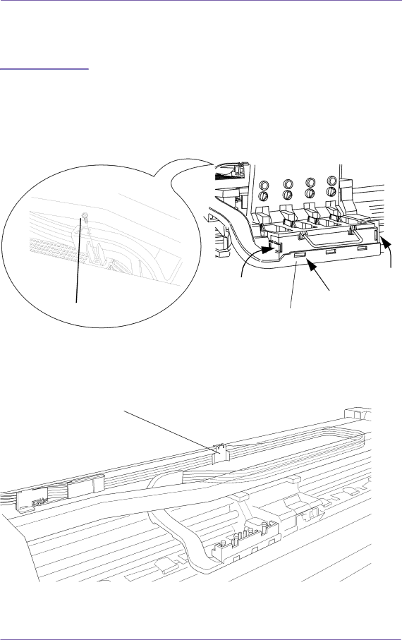
For the following steps, refer to Figure
Tail Deflectors and Rear Platen
Left and Right Rear Covers
For steps 2 to 7, refer to Figure
Be very careful when disconnecting the Trailing Cable from
Cable and then it will need replacing
For the following steps, refer to Figure
When reconnecting the Trailing Cable to the Electronics
Installation of the Electronics Module
Removal and Installation
Module, make sure you connect it correctly as follows
After the installation of the Electronics Module
Media Sensor
Window
Window
Top Cover
Top Cover
Back Cover
Back Cover
Scan-axisMotor Assembly
Scan-axis Motor Assembly
Encoder Strip
Encoder Strip
For steps 4 and 5, refer to Figure
Clip item 2 in towards the middle of the printer
C607411
Tensioner Assembly
Tensioner
For steps 4 to 6, refer to Figure
Trailing Cable
For steps 2 to 5, refer to Figure
Installation of the Trailing Cable
C607440
Cutter Assembly
Cutter Assembly
For steps 3 and 4, refer to Figure
Carriage Assembly and Belt
Carriage Assembly and Belt
For steps 3 and 4, refer to Figure
For steps 6 to 8, refer to Figure
C607415
For steps 11 and 12, refer to Figure
For steps 13 to 15, refer to Figure
With a spring item 2. When removing the carriage assembly
Rear bushing item 1 on the carriage assembly is tensioned
Item 3 hold the rear bushing on the carriage assembly
Installation of the Carriage Assembly
Please take note of the following steps when installing
You must perform the following Service Calibrations after
Installation of the Carriage Assembly
Tubes System Assembly
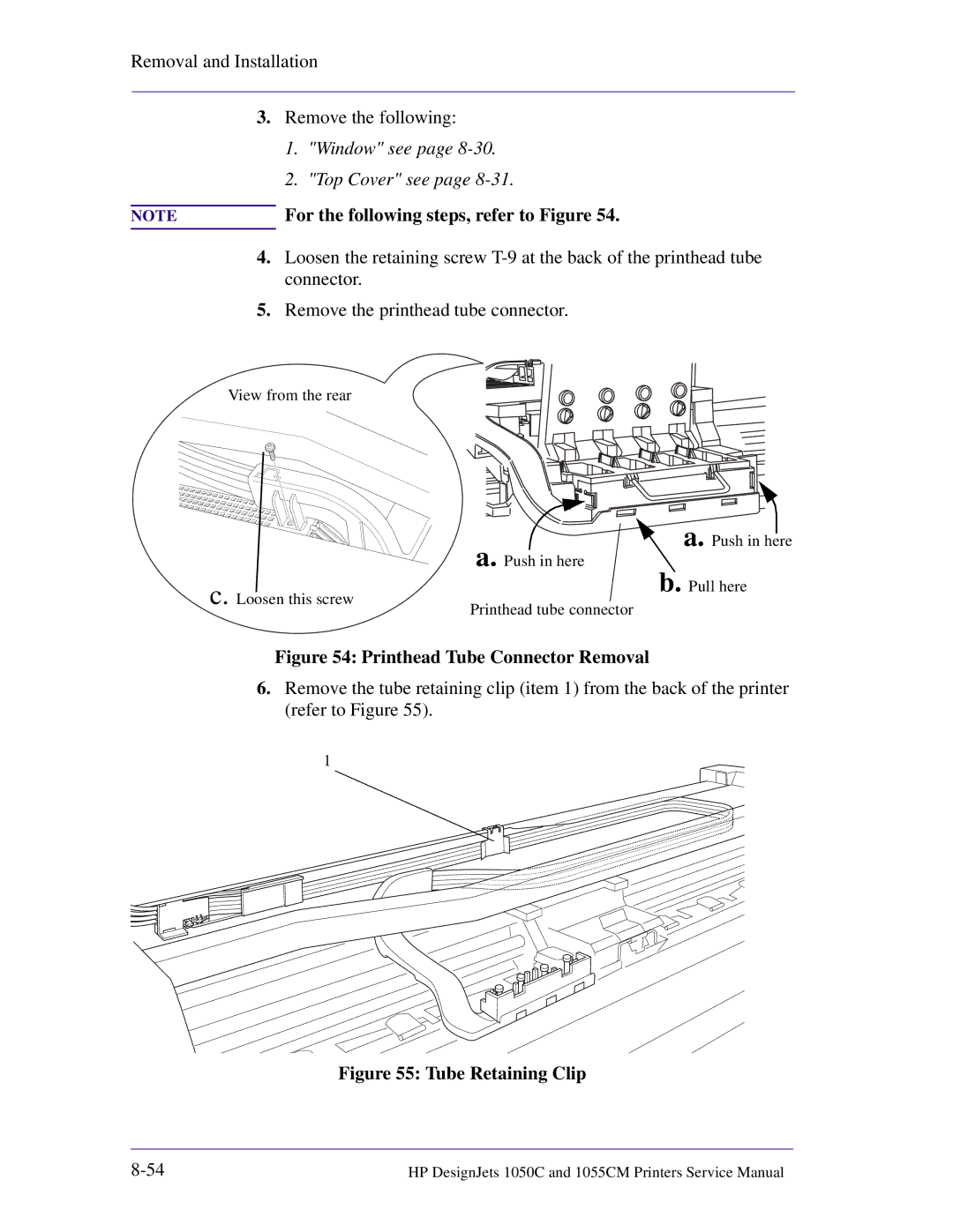
Printhead Tube Connector Removal
Working from the rear of the printer
Latches
Ink Cartridge Tube Connector Cable
Ink Cartridge Tube Connector pulled out
Restarting the printer
Ink Leak Detector Assembly
Leak Detector Cable
Front Platen Assembly
Platen Assembly
Installation of the Platen Assembly
Paper Entry Assembly
Entry Roller
Linkage Rod
Roller Guide
Platen Mounts
Left Electronic Module Mount
For the following steps refer to Figure
Media Holder Strip
Media Holder Strip
Installation of the Drive Roller
Drive Roller
Center Guide
Left Hand Center Guide Screws
Supporting the center guide in place
For re-installation purposes, note the position of the pins
Working from the front of the printer
Pinch-Wheel Assembly and Cam
Pinch Wheel Cam
Assemblies item 2 to the underneath of the scan axis
For steps 3 and 4 refer to Figure
Remove the twelve T-15 screws item 1 securing the pinch-arm
Screws also secure the pinch-wheel cam to the printer
Preventive Maintenance
Preventive Maintenance
Scheduled Maintenance
Cleaning the Overdrive
Level of Printer Usage
Preventive Maintenance Kit Part Number C6072-60143
Scan-axis Maintenance
Maintenance Advised
Most important parts to keep clean are the upper
Functional Overview
HP DesignJet 1055CM printer
HP DesignJet 1050C Printer
Electrical System
Power Supply Unit PSU
Voltage Maximum Output Systems
Printer Cancel and Form Feed and Cut
Soft Power-Off Switch
Front Panel
Ink Delivery System IDS
Ink Supply Station ISS
Tubes System
Air Pressurization System APS
Ink Level Sense ILS
Leak Detect System LDS
Service Station
Print Head Cleaner PHC
Wiper
Cap
Spittoon
Snout Wiper
Handle and Printable Label
Printer Specifications
Functional Specifications
10-13
Temperature it may stop to protect its ink systems
At 3000m altitude the printer may have operational problems
10-15
Printable Area
Ansi paper
Interface Specifications
For manufacturing purposes only and cannot be used to print
Electro-Magnetic Compatibility EMC
To Obtain a Material Safety Data Sheet Msds Sound
Regulatory Notices
LpA 70 dB, am Arbeitsplatz, im Normalbetrieb, nach DIN
FCC How to Identify and Resolve Radio-TV Interference
10-20
10-21
Declaration of Conformity
10-23
10-24
Application
Default
Ansi size
Centronics
Inked area Matte
Margin
Input/output
Media
Platen
Raster
Pen
Printing area
Glossary
Index
Page
Page
Page
Page
Index Index-6
About this Edition
DesignJet 1050C/1055CM