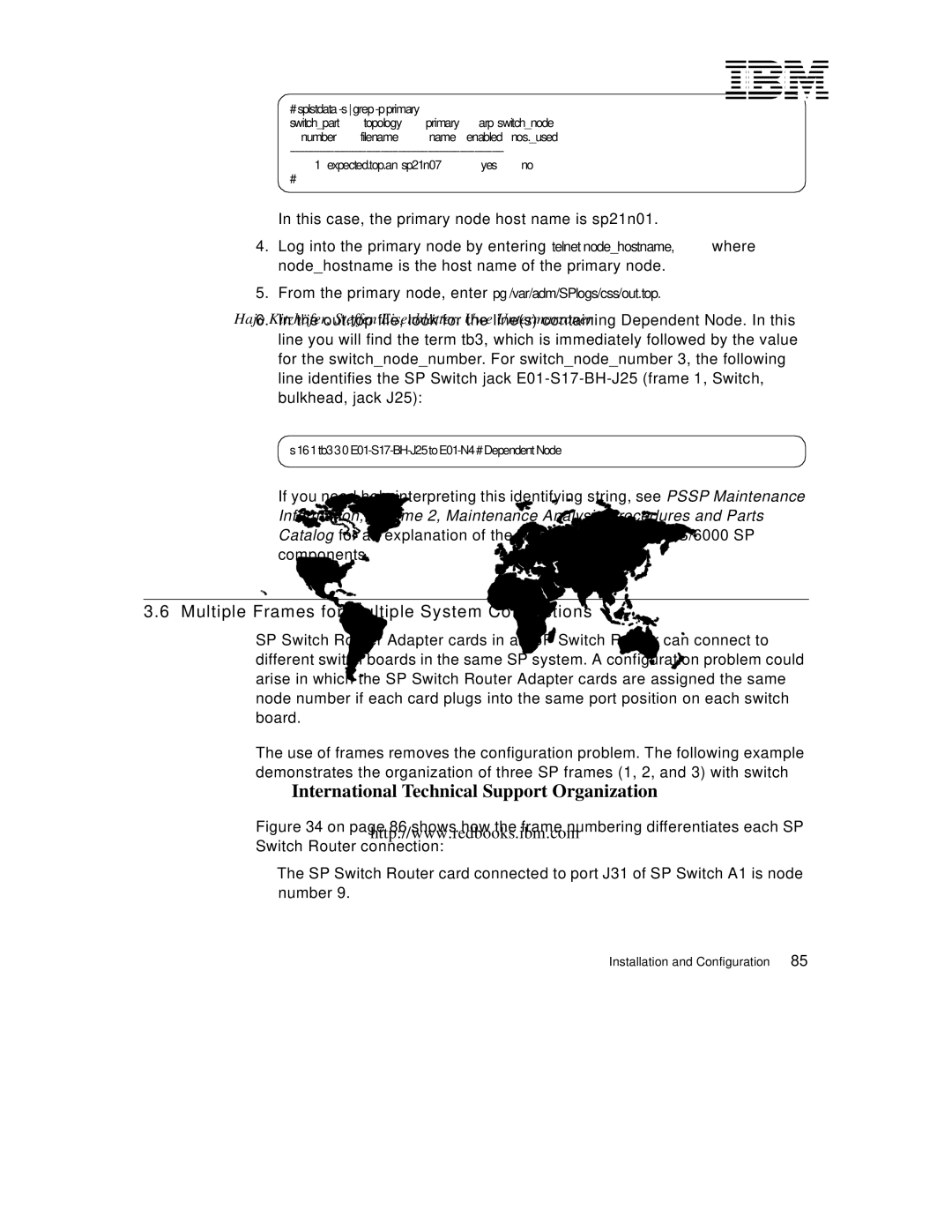
# splstdata |
|
|
| |
switch_part | topology | primary | arp | switch_node |
number | filename | name | enabled | nos._used |
1 expected.top.an sp21n07 | yes | no |
# |
|
|
In this case, the primary node host name is sp21n01.
4.Log into the primary node by entering telnet node_hostname, where node_hostname is the host name of the primary node.
5.From the primary node, enter pg /var/adm/SPlogs/css/out.top.
6.In the out.top file, look for the line(s) containing Dependent Node. In this line you will find the term tb3, which is immediately followed by the value for the switch_node_number. For switch_node_number 3, the following line identifies the SP Switch jack
s 16 1 tb3 3 0
If you need help interpreting this identifying string, see PSSP Maintenance Information, Volume 2, Maintenance Analysis Procedures and Parts Catalog for an explanation of the naming standard for RS/6000 SP components.
3.6 Multiple Frames for Multiple System Connections
SP Switch Router Adapter cards in an SP Switch Router can connect to different switch boards in the same SP system. A configuration problem could arise in which the SP Switch Router Adapter cards are assigned the same node number if each card plugs into the same port position on each switch board.
The use of frames removes the configuration problem. The following example demonstrates the organization of three SP frames (1, 2, and 3) with switch boards in each.
Figure 34 on page 86 shows how the frame numbering differentiates each SP Switch Router connection:
•The SP Switch Router card connected to port J31 of SP Switch A1 is node number 9.
Installation and Configuration | 85 |