•By a logical interface number assigned after the SAS/DAS settings are numbered (used in the /etc/grifconfig.conf file)
•By a unique IP address assigned to each logical interface
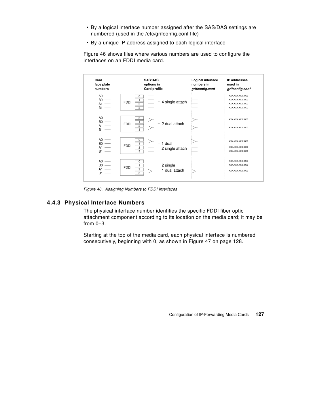
Figure 46 shows files where various numbers are used to configure the interfaces on an FDDI media card.
Card face plate numbers
A0
B0
A1
B1
A0
B0
A1
0
1
FDDI ![]() 2
2
3
0
1
FDDI ![]() 2
2
SAS/DAS | Logical interface | IP addresses | |||
options in | numbers in | used in | |||
Card profile | grifconfig.conf | grifconfig.conf | |||
|
|
|
|
| xxx.xxx.xxx.xxx |
|
|
|
|
| |
|
| 4 single attach |
|
| xxx.xxx.xxx.xxx |
|
|
|
| xxx.xxx.xxx.xxx | |
|
|
|
|
| xxx.xxx.xxx.xxx |
|
|
|
|
| |
|
|
|
|
| xxx.xxx.xxx.xxx |
|
| 2 dual attach |
|
| xxx.xxx.xxx.xxx |
|
|
|
| ||
|
|
|
|
| |
B1
A0
B0
A1
B1
A0
B0
A1
B1
FDDI
FDDI
3
0
1
2
3
0
1
2
3
1 dual | xxx.xxx.xxx.xxx | |
xxx.xxx.xxx.xxx | ||
2 single attach | ||
xxx.xxx.xxx.xxx | ||
| ||
| xxx.xxx.xxx.xxx | |
2 single | xxx.xxx.xxx.xxx | |
1 dual attach | xxx.xxx.xxx.xxx |
Figure 46. Assigning Numbers to FDDI Interfaces
4.4.3 Physical Interface Numbers
The physical interface number identifies the specific FDDI fiber optic attachment component according to its location on the media card; it may be from
Starting at the top of the media card, each physical interface is numbered consecutively, beginning with 0, as shown in Figure 47 on page 128.
Configuration of | 127 |