header. The media card reads the header only if told to do so by information in the HIPPI I-field. If the I-field tells the card to read the IP header, then an IP connection is established.

4.5.1.3 How the I-field is Used
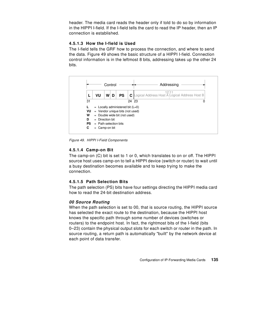
The I-field tells the GRF how to process the connection, and where to send the data. Figure 49 shows the basic structure of a HIPPI I-field. Connection control information is in the leftmost 8 bits, addressing takes up the other 24 bits.

Control

Addressing

L

VU

W D

PS

12 11

CLogical Address Host A Logical Address Host B

31

24

23

0

L= Locally administered bit (L=0) VU = Vendor unique bits (not used) W = Double wide bit (not used)

D = Direction bit

PS = Path selection bits C = Camp-on bit

Figure 49. HIPPI I-Field Components

4.5.1.4 Camp-on Bit

The camp-on (C) bit is set to 1 or 0, which translates to on or off. The HIPPI source host uses camp-on to tell a HIPPI device (switch or router) to wait until a busy destination becomes available and to keep trying to make the connection.

4.5.1.5 Path Selection Bits

The path selection (PS) bits have four settings directing the HIPPI media card how to read the 24-bit destination address.

00 Source Routing

When the path selection is set to 00, that is source routing, the HIPPI source has selected the exact route to the destination, because the HIPPI host knows the specific path through some number of devices (switches or routers) to the endpoint host. In fact, the rightmost bits of the I-field (bits 0–23) contain the physical output slots for each switch or router in the path. In source routing, a return path is automatically "built" by the network device at each point of data transfer.

Configuration of IP-Forwarding Media Cards

135

Page 153
Image 153
Lexmark IBM 9077 manual How the I-field is Used, Camp-on Bit, Path Selection Bits, 135