bridge_group bg0 {
port gf000 gf001 gf002 gf003;
};
This is the simplest bridge definition that worked in our scenario. Many additional parameters can be set. See Section 4.6.9.3, “Editing Utility – Bredit” on page 146 for further details.
•Assign an IP address:
Open /etc/grifconfig.conf. Comment out all former FDDI interface definitions by inserting a # at the beginning of the respective lines. Define the new bridge group and assign an IP address that is in the same subnet as all four FDDI backbones:
bg0 | 10.10.1.13 | 255.255.255.0 - | mtu 4352 |
Save /etc/grifconfig.conf. Issue grwrite
Note: According to GRF Configuration Guide 1.4,
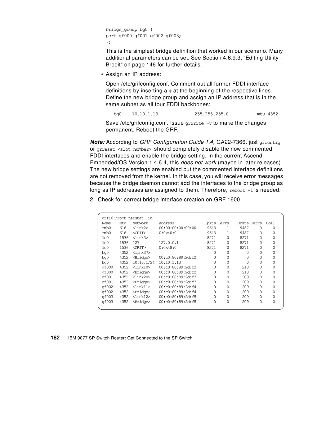
2. Check for correct bridge interface creation on GRF 1600:
grf16:/root netstat |
|
|
|
|
|
| ||
Name | Mtu | Network | Address | Ipkts Ierrs | Opkts Oerrs | Coll | ||
rmb0 | 616 | <link2> | 00:00:00:00:00:00 | 9643 | 1 | 9487 | 0 | 0 |
rmb0 | 616 | <GRIT> | 0:0x40:0 | 9643 | 1 | 9487 | 0 | 0 |
lo0 | 1536 | <link3> |
| 8271 | 0 | 8271 | 0 | 0 |
lo0 | 1536 | 127 | 127.0.0.1 | 8271 | 0 | 8271 | 0 | 0 |
lo0 | 1536 | <GRIT> | 0:0x48:0 | 8271 | 0 | 8271 | 0 | 0 |
bg0 | 4352 | <link37> |
| 0 | 0 | 0 | 0 | 0 |
bg0 | 4352 | <Bridge> | 00:c0:80:89:2d:f2 | 0 | 0 | 0 | 0 | 0 |
bg0 | 4352 | 10.10.1/24 | 10.10.1.13 | 0 | 0 | 0 | 0 | 0 |
gf000 | 4352 | <link10> | 00:c0:80:89:2d:f2 | 0 | 0 | 210 | 0 | 0 |
gf000 | 4352 | <Bridge> | 00:c0:80:89:2d:f2 | 0 | 0 | 210 | 0 | 0 |
gf001 | 4352 | <link20> | 00:c0:80:89:2d:f3 | 0 | 0 | 209 | 0 | 0 |
gf001 | 4352 | <Bridge> | 00:c0:80:89:2d:f3 | 0 | 0 | 209 | 0 | 0 |
gf002 | 4352 | <link11> | 00:c0:80:89:2d:f4 | 0 | 0 | 209 | 0 | 0 |
gf002 | 4352 | <Bridge> | 00:c0:80:89:2d:f4 | 0 | 0 | 209 | 0 | 0 |
gf003 | 4352 | <link12> | 00:c0:80:89:2d:f5 | 0 | 0 | 209 | 0 | 0 |
gf003 | 4352 | <Bridge> | 00:c0:80:89:2d:f5 | 0 | 0 | 209 | 0 | 0 |