Performance:
To get a rough overview of the data transfer rates that can be achieved in this scenario, the following test was performed:
1.We used ftp to conduct several file transfers of a 300 MB file from the nodes in SP2 to one chosen node in SP21, and at the same time used ftp to conduct several file transfers of a 300 MB file from the nodes in SP21 to a chosen node in SP2. We sent the files to /dev/null on the receiving node to eliminate any hard disk influence.
We saw up to about 14.5 MB/s with just one side sending data; with all nodes sending and receiving, we achieved an duplex throughput of about 24 MB/s on the ATM port.
So it just might turn out that one 155 Mbit ATM port is not enough for a performance connection between two SP systems.
7.1.2 ATM OC-3c Backbone - Using Two Ports
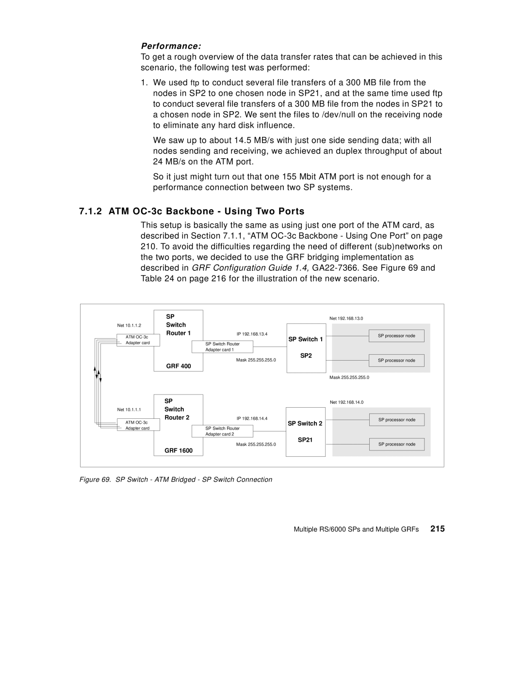
This setup is basically the same as using just one port of the ATM card, as described in Section 7.1.1, “ATM
210.To avoid the difficulties regarding the need of different (sub)networks on the two ports, we decided to use the GRF bridging implementation as described in GRF Configuration Guide 1.4,
| SP |
| Net 192.168.13.0 |
Net 10.1.1.2 | Switch |
|
|
ATM | Router 1 | IP 192.168.13.4 | SP processor node |
Adapter card |
| SP Switch Router | SP Switch 1 |
|
| ||
|
| Adapter card 1 | SP2 |
|
| Mask 255.255.255.0 | |
| GRF 400 | SP processor node | |
|
|
| |
|
|
| Mask 255.255.255.0 |
| SP |
| Net 192.168.14.0 |
Net 10.1.1.1 | Switch |
|
|
| Router 2 | IP 192.168.14.4 | SP processor node |
ATM |
|
| SP Switch 2 |
Adapter card |
| SP Switch Router |
|
|
| Adapter card 2 | SP21 |
|
| Mask 255.255.255.0 | |
|
| SP processor node | |
| GRF 1600 |
|
|
Figure 69. SP Switch - ATM Bridged - SP Switch Connection
Multiple RS/6000 SPs and Multiple GRFs 215
