Lexmark IBM 9077 Installation and Configuration, Connecting the GRF to the SP Switch and the CWS

Models: IBM 9077

1 342
Download 342 pages 50.2 Kb
Page 87
Image 87

Chapter 3. Installation and Configuration

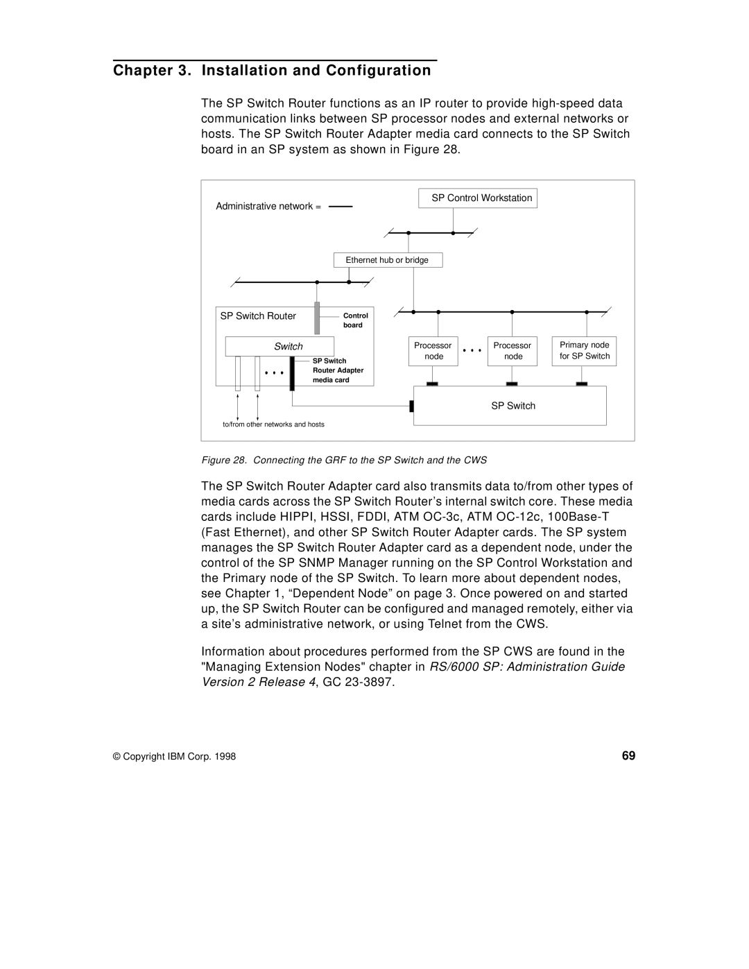
The SP Switch Router functions as an IP router to provide high-speed data communication links between SP processor nodes and external networks or hosts. The SP Switch Router Adapter media card connects to the SP Switch board in an SP system as shown in Figure 28.

Administrative network =

SP Control Workstation


Ethernet hub or bridge


SP Switch Router

Control


board


Switch


Processor

Processor

Primary node


SP Switch

node

node

for SP Switch


Router Adapter


media card


SP Switch


to/from other networks and hosts


Figure 28. Connecting the GRF to the SP Switch and the CWS

The SP Switch Router Adapter card also transmits data to/from other types of media cards across the SP Switch Router’s internal switch core. These media cards include HIPPI, HSSI, FDDI, ATM OC-3c, ATM OC-12c, 100Base-T (Fast Ethernet), and other SP Switch Router Adapter cards. The SP system manages the SP Switch Router Adapter card as a dependent node, under the control of the SP SNMP Manager running on the SP Control Workstation and the Primary node of the SP Switch. To learn more about dependent nodes, see Chapter 1, “Dependent Node” on page 3. Once powered on and started up, the SP Switch Router can be configured and managed remotely, either via a site’s administrative network, or using Telnet from the CWS.

Information about procedures performed from the SP CWS are found in the "Managing Extension Nodes" chapter in RS/6000 SP: Administration Guide Version 2 Release 4, GC 23-3897.

© Copyright IBM Corp. 1998

69

Page 87
Image 87
Lexmark IBM 9077 manual Installation and Configuration, Connecting the GRF to the SP Switch and the CWS