To successfully run this configuration, all four ports of the SP Switch Router FDDI media card have to be assigned IP addresses in different subnets. Otherwise, only port A0 will be activated.
Note: Every port of the SP Switch Router FDDI media card has to be assigned to a different subnet when bridging is not configured (see Section 5.1.4.2, “SP Switch - FDDI Connection with Bridging” on page 179).
In this sample configuration no routes need to be set on the SP Switch Router. Node
1.On all four nodes in SP2 with an FDDI interface, add the route to the SP Switch network of SP21:
•On node 9 in SP2, add this route:
route add
•On node 10 in SP2, add this route:
route add
•On node 11in SP2, add this route:
route add
•On node 12 in SP2, add this route:
route add
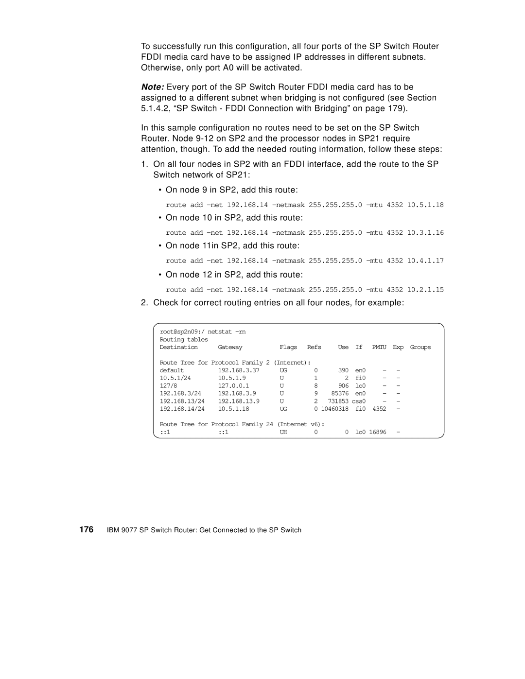
2.Check for correct routing entries on all four nodes, for example:
root@sp2n09:/ netstat |
|
|
|
|
|
|
| |
Routing tables |
|
|
|
|
|
|
|
|
Destination | Gateway | Flags | Refs | Use | If | PMTU | Exp Groups | |
Route Tree for Protocol Family 2 (Internet): |
|
|
|
|
| |||
default | 192.168.3.37 | UG | 0 |
| 390 | en0 | - | - |
10.5.1/24 | 10.5.1.9 | U | 1 |
| 2 | fi0 | - | - |
127/8 | 127.0.0.1 | U | 8 |
| 906 | lo0 | - | - |
192.168.3/24 | 192.168.3.9 | U | 9 |
| 85376 | en0 | - | - |
192.168.13/24 | 192.168.13.9 | U | 2 |
| 731853 | css0 | - | - |
192.168.14/24 | 10.5.1.18 | UG | 0 | 10460318 | fi0 | 4352 | - | |
Route Tree for Protocol Family 24 (Internet v6): |
|
|
|
| ||||
::1 | ::1 | UH | 0 |
| 0 | lo0 16896 | - | |