Additionally, the RS232 port (which is not shown in the figure) allows you to connect the VT100 console by using an RS232 null modem cable. The console and cable must be supplied by the user.
2.3.4 Memory Guidelines for the IP Switch Control Board
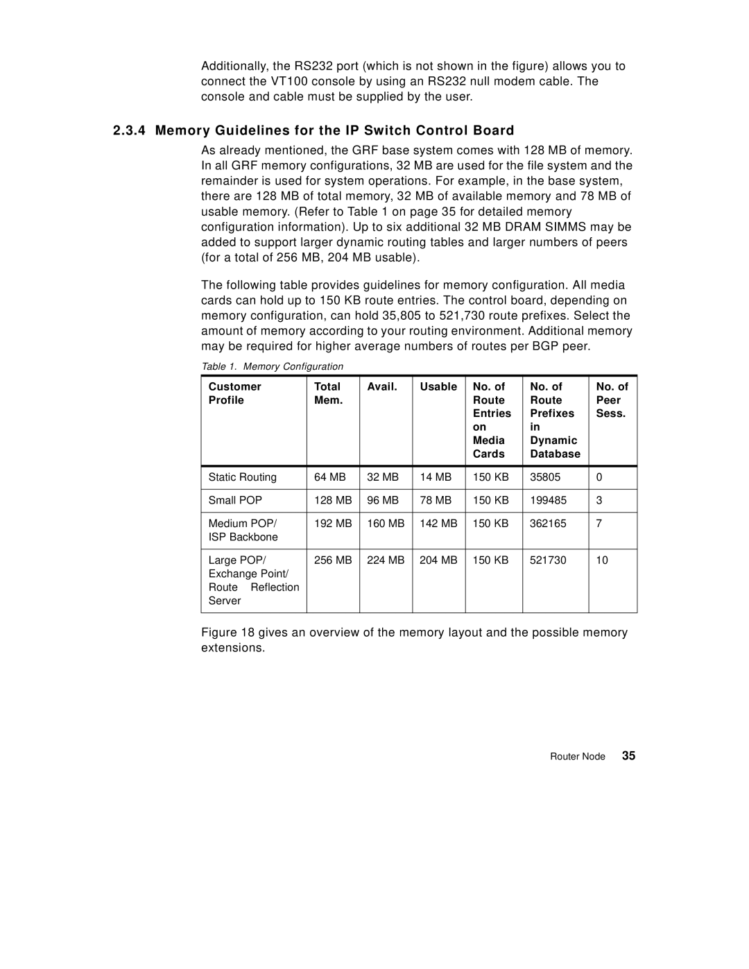
As already mentioned, the GRF base system comes with 128 MB of memory. In all GRF memory configurations, 32 MB are used for the file system and the remainder is used for system operations. For example, in the base system, there are 128 MB of total memory, 32 MB of available memory and 78 MB of usable memory. (Refer to Table 1 on page 35 for detailed memory configuration information). Up to six additional 32 MB DRAM SIMMS may be added to support larger dynamic routing tables and larger numbers of peers (for a total of 256 MB, 204 MB usable).
The following table provides guidelines for memory configuration. All media cards can hold up to 150 KB route entries. The control board, depending on memory configuration, can hold 35,805 to 521,730 route prefixes. Select the amount of memory according to your routing environment. Additional memory may be required for higher average numbers of routes per BGP peer.
Table 1. | Memory Configuration |
|
|
|
|
| |
Customer | Total | Avail. | Usable | No. of | No. of | No. of | |
Profile | Mem. |
|
| Route | Route | Peer | |
|
|
|
|
| Entries | Prefixes | Sess. |
|
|
|
|
| on | in |
|
|
|
|
|
| Media | Dynamic |
|
|
|
|
|
| Cards | Database |
|
|
|
|
|
|
|
| |
Static Routing | 64 MB | 32 MB | 14 MB | 150 KB | 35805 | 0 | |
|
|
|
|
|
|
| |
Small POP | 128 MB | 96 MB | 78 MB | 150 KB | 199485 | 3 | |
|
|
|
|
|
|
| |
Medium POP/ | 192 MB | 160 MB | 142 MB | 150 KB | 362165 | 7 | |
ISP Backbone |
|
|
|
|
|
| |
|
|
|
|
|
|
| |
Large POP/ | 256 MB | 224 MB | 204 MB | 150 KB | 521730 | 10 | |
Exchange Point/ |
|
|
|
|
|
| |
Route | Reflection |
|
|
|
|
|
|
Server |
|
|
|
|
|
|
|
|
|
|
|
|
|
|
|
Figure 18 gives an overview of the memory layout and the possible memory extensions.
Router Node 35