With this scenario and without further tuning (refer to Appendix A, “Laboratory Hardware and Software Configuration” on page 233 for actual no parameters), we measured a stable cumulative transfer rate of up to 83 MB/s (observed with the freeware tool monitor). This was the maximum transfer rate achievable in our environment. We are confident that further tuning and faster nodes can achieve higher transfer rates up to the maximum of GRFs crosspoint switch which is 100 MB/s.
6.2 Sharing Network Resources
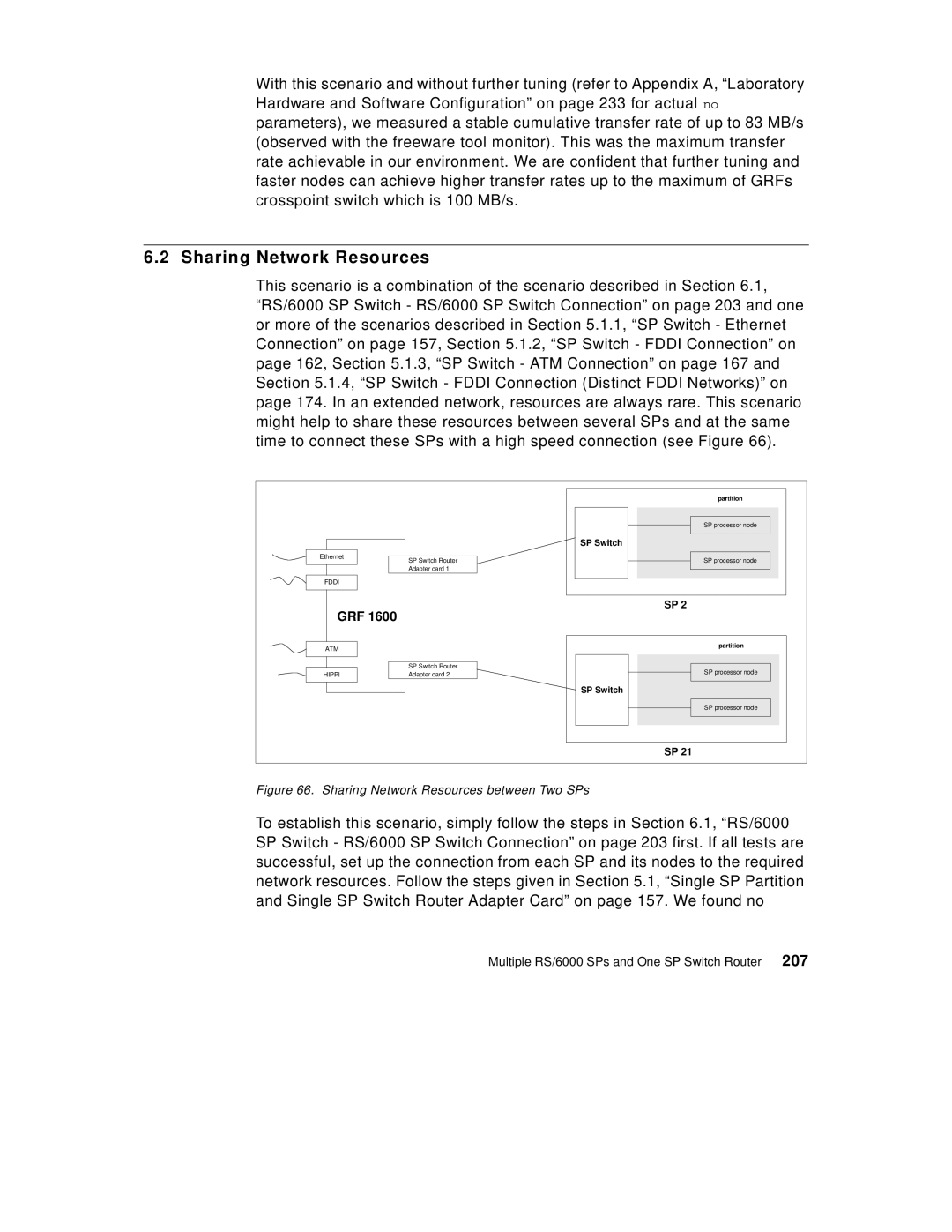
This scenario is a combination of the scenario described in Section 6.1, “RS/6000 SP Switch - RS/6000 SP Switch Connection” on page 203 and one or more of the scenarios described in Section 5.1.1, “SP Switch - Ethernet Connection” on page 157, Section 5.1.2, “SP Switch - FDDI Connection” on page 162, Section 5.1.3, “SP Switch - ATM Connection” on page 167 and Section 5.1.4, “SP Switch - FDDI Connection (Distinct FDDI Networks)” on page 174. In an extended network, resources are always rare. This scenario might help to share these resources between several SPs and at the same time to connect these SPs with a high speed connection (see Figure 66).
|
| partition | |
|
| SP processor node | |
|
| SP Switch | |
Ethernet | SP Switch Router | SP processor node | |
| |||
| Adapter card 1 |
| |
FDDI |
|
| |
GRF 1600 |
| SP 2 | |
|
| ||
ATM |
| partition | |
|
| ||
| SP Switch Router | SP processor node | |
HIPPI | Adapter card 2 | ||
| |||
|
| SP Switch | |
|
| SP processor node | |
|
| SP 21 |
Figure 66. Sharing Network Resources between Two SPs
To establish this scenario, simply follow the steps in Section 6.1, “RS/6000 SP Switch - RS/6000 SP Switch Connection” on page 203 first. If all tests are successful, set up the connection from each SP and its nodes to the required network resources. Follow the steps given in Section 5.1, “Single SP Partition and Single SP Switch Router Adapter Card” on page 157. We found no
Multiple RS/6000 SPs and One SP Switch Router 207