Chapter 7. Multiple RS/6000 SPs and Multiple GRFs
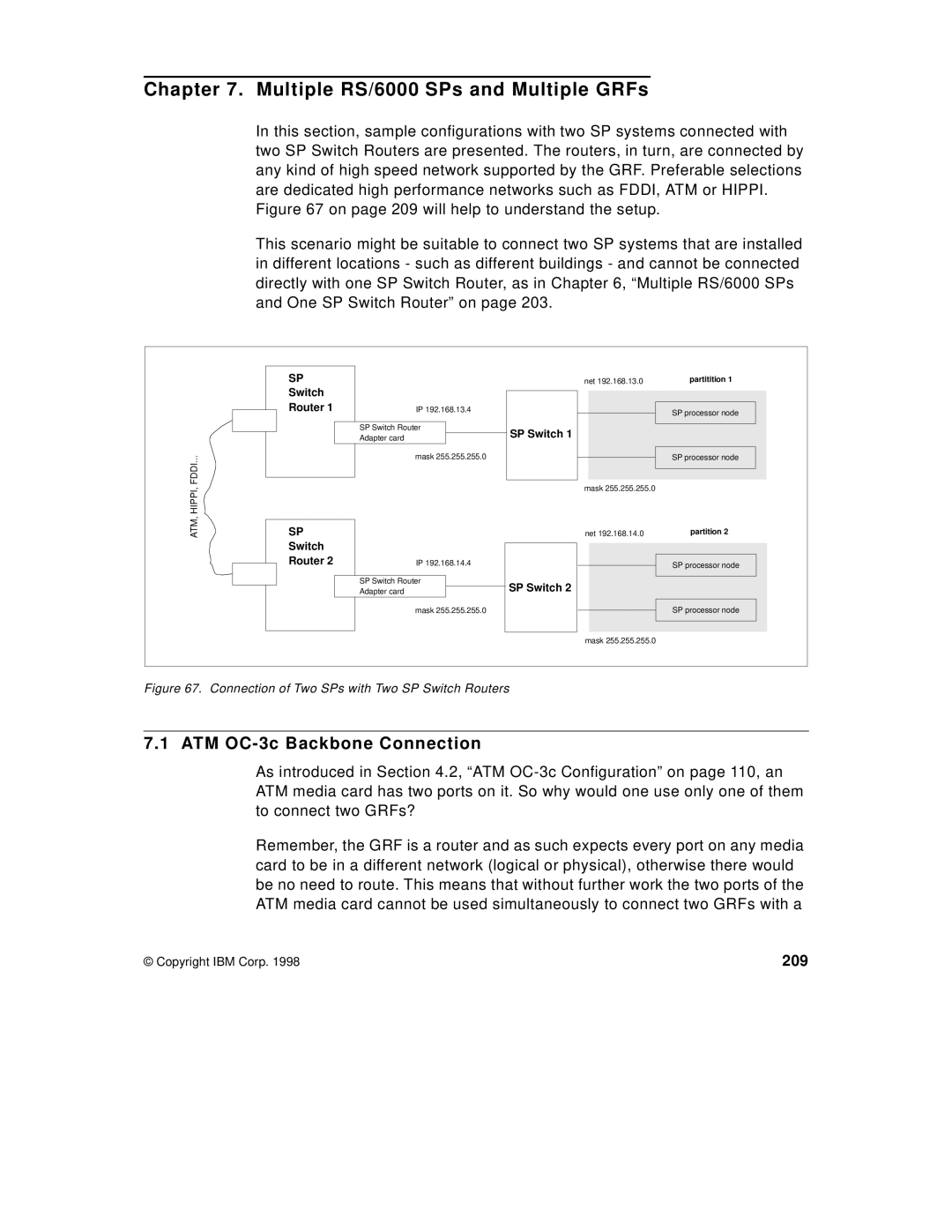
In this section, sample configurations with two SP systems connected with two SP Switch Routers are presented. The routers, in turn, are connected by any kind of high speed network supported by the GRF. Preferable selections are dedicated high performance networks such as FDDI, ATM or HIPPI. Figure 67 on page 209 will help to understand the setup.
This scenario might be suitable to connect two SP systems that are installed in different locations - such as different buildings - and cannot be connected directly with one SP Switch Router, as in Chapter 6, “Multiple RS/6000 SPs and One SP Switch Router” on page 203.
| SP | net 192.168.13.0 | partitition 1 |
| Switch |
|
|
| Router 1 | IP 192.168.13.4 | SP processor node |
|
|
| |
| SP Switch Router |
| |
| Adapter card | SP Switch 1 |
|
... |
| mask 255.255.255.0 | SP processor node |
FDDI |
| mask 255.255.255.0 |
|
ATM, HIPPI, |
|
| |
SP | net 192.168.14.0 | partition 2 | |
| Switch |
|
|
| Router 2 | IP 192.168.14.4 | SP processor node |
|
|
| |
| SP Switch Router |
| |
| Adapter card | SP Switch 2 |
|
|
| mask 255.255.255.0 | SP processor node |
|
| mask 255.255.255.0 |
|
Figure 67. Connection of Two SPs with Two SP Switch Routers
7.1 ATM OC-3c Backbone Connection
As introduced in Section 4.2, “ATM
Remember, the GRF is a router and as such expects every port on any media card to be in a different network (logical or physical), otherwise there would be no need to route. This means that without further work the two ports of the ATM media card cannot be used simultaneously to connect two GRFs with a
© Copyright IBM Corp. 1998 | 209 |