Configuration assumptions:
•The SP Switch Router Ethernet media card has been installed according to Section 4.1, “Ethernet
•The SP Switch Router Adapter card has been installed according to Section 3.7,
•The SP Switch Router Adapter card and SP processor node Switch adapters are in the same IP subnet.
•ARP should be enabled on the SP Switch network to provide the most flexibility in assigning IP addresses (strongly recommended!).
•If ARP is disabled on the SP Switch network, the IP addresses assigned to the nodes must be determined by the Switch node numbers. Refer to PSSP Planning, Volume 2, Control Workstation and Software Environment for details.
Configuration:
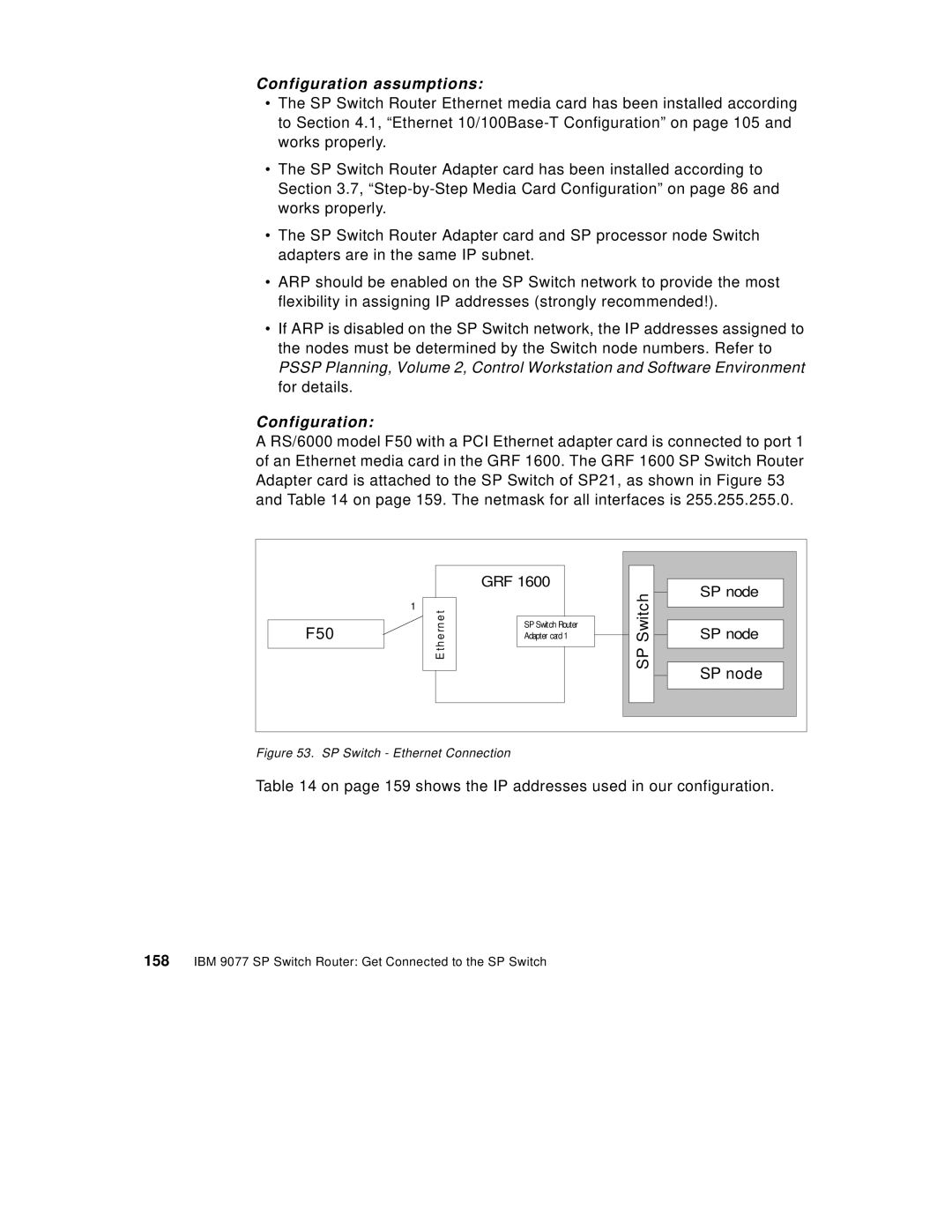
A RS/6000 model F50 with a PCI Ethernet adapter card is connected to port 1 of an Ethernet media card in the GRF 1600. The GRF 1600 SP Switch Router Adapter card is attached to the SP Switch of SP21, as shown in Figure 53 and Table 14 on page 159. The netmask for all interfaces is 255.255.255.0.
| GRF 1600 |
| SP node |
|
| SP Switch | |
1 |
|
| |
F50 | SP Switch Router | SP node | |
Adapter card 1 | |||
E thrneet |
| SP node | |
|
|
|
Figure 53. SP Switch - Ethernet Connection
Table 14 on page 159 shows the IP addresses used in our configuration.