Return to Section TOC
Return to Section TOC
Return to Master TOC
Return to Master TOC
TROUBLESHOOTING AND REPAIR |
WIRE FEEDER CONTROL BOARD REMOVAL AND REPLACEMENT (continued)
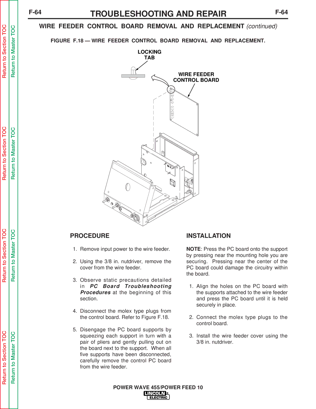
FIGURE F.18 — WIRE FEEDER CONTROL BOARD REMOVAL AND REPLACEMENT.
LOCKING
TAB
WIRE FEEDER
CONTROL BOARD
Return to Section TOC
Return to Section TOC
Return to Master TOC
Return to Master TOC
PROCEDURE
1.Remove input power to the wire feeder.
2.Using the 3/8 in. nutdriver, remove the cover from the wire feeder.
3.Observe static precautions detailed in PC Board Troubleshooting Procedures at the beginning of this section.
4.Disconnect the molex type plugs from the control board. Refer to Figure F.18.
5.Disengage the PC board supports by squeezing each support in turn with a pair of pliers and gently pulling out on the board next to the support. When all five supports have been disconnected, carefully remove the control PC board from the wire feeder.
INSTALLATION
NOTE: Press the PC board onto the support by pressing near the mounting hole you are securing. Pressing near the center of the PC board could damage the circuitry within the board.
1.Align the holes on the PC board with the supports attached to the wire feeder and press the PC board until it is held securely in place.
2.Connect the molex type plugs to the control board.
3.Install the wire feeder cover using the 3/8 in. nutdriver.
