Return to Master TOC
Return to Master TOC
Return to Master TOC
Return to Master TOC
THEORY OF OPERATION | |
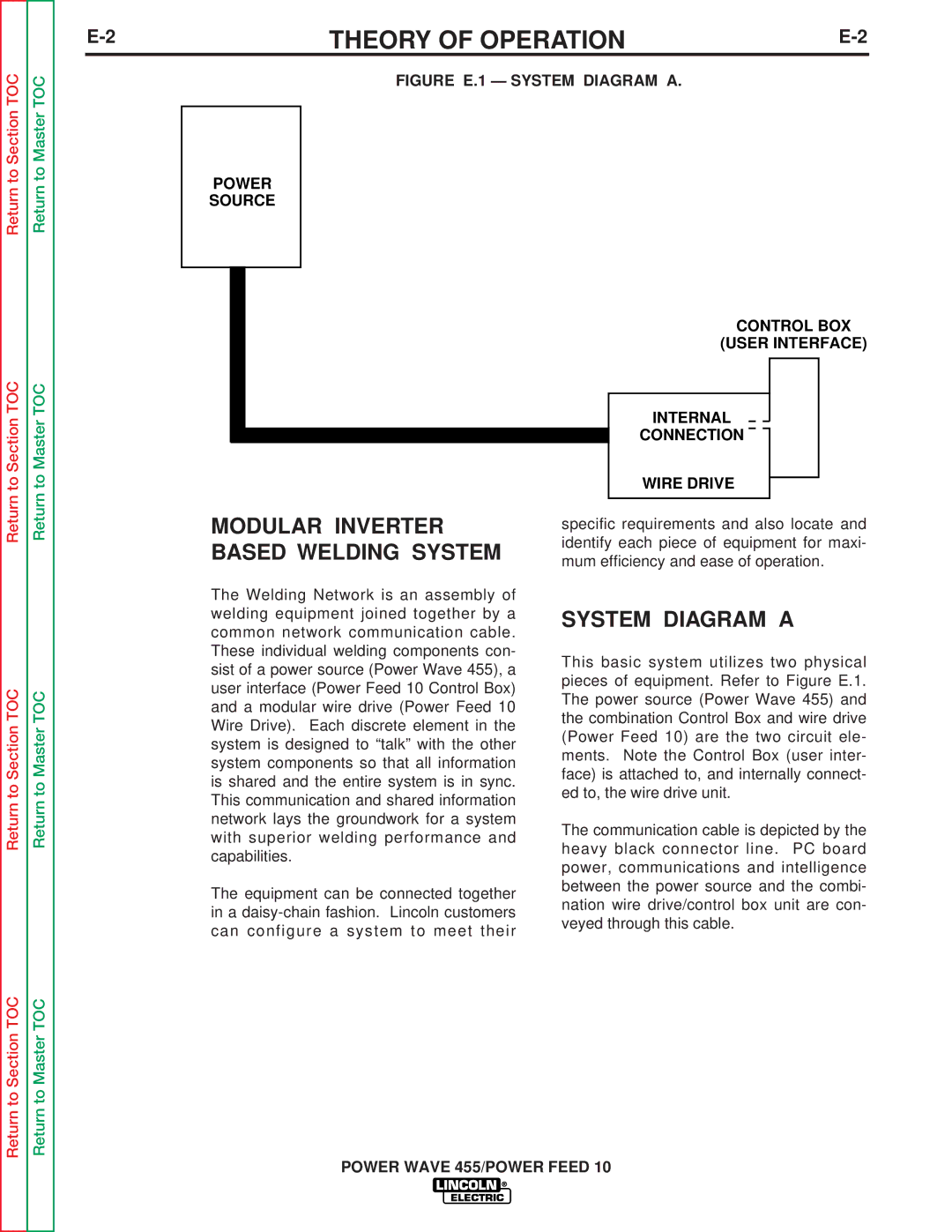
FIGURE E.1 — SYSTEM DIAGRAM A. |
|
POWER
SOURCE
CONTROL BOX
(USER INTERFACE)
|
|
|
|
|
|
|
|
|
| |
|
|
|
| INTERNAL |
|
|
|
|
| |
|
|
|
|
|
|
|
| |||
|
|
|
| CONNECTION |
|
|
|
|
| |
MODULAR INVERTER |
| WIRE DRIVE |
|
| ||||||
|
|
| ||||||||
|
|
|
|
|
|
| ||||
specific requirements and also locate and | ||||||||||
BASED WELDING SYSTEM | identify each piece of equipment for maxi- | |||||||||
mum efficiency and ease of operation. | ||||||||||
|
|
| ||||||||
The Welding Network is an assembly of |
|
|
|
|
|
|
| |||
welding equipment joined together by a | SYSTEM DIAGRAM A | |||||||||
common network communication cable. | ||||||||||
|
|
|
|
|
|
| ||||
These individual welding components con- | This basic system utilizes two physical | |||||||||
sist of a power source (Power Wave 455), a | ||||||||||
pieces of equipment. Refer to Figure E.1. | ||||||||||
user interface (Power Feed 10 Control Box) | ||||||||||
The power source (Power Wave 455) and | ||||||||||
and a modular wire drive (Power Feed 10 | ||||||||||
the combination Control Box and wire drive | ||||||||||
Wire Drive). Each discrete element in the | ||||||||||
(Power Feed 10) are the two circuit ele- | ||||||||||
system is designed to “talk” with the other | ||||||||||
ments. Note the Control Box (user inter- | ||||||||||
system components so that all information | ||||||||||
face) is attached to, and internally connect- | ||||||||||
is shared and the entire system is in sync. | ||||||||||
ed to, the wire drive unit. | ||||||||||
This communication and shared information | ||||||||||
|
|
|
|
|
|
| ||||
network lays the groundwork for a system | The communication cable is depicted by the | |||||||||
with superior welding performance and | ||||||||||
heavy black connector line. PC board | ||||||||||
capabilities. | ||||||||||
power, communications and intelligence | ||||||||||
|
|
| ||||||||
The equipment can be connected together | between the power source and the combi- | |||||||||
nation wire drive/control box unit are con- | ||||||||||
in a | ||||||||||
veyed through this cable. | ||||||||||
can configure a system to meet their | ||||||||||
|
|
|
|
|
|
| ||||
POWER WAVE 455/POWER FEED 10