OPERATION |
DUTY CYCLE AND WELDING
CAPABILITIES
The Power Feed 10 wire feeder is capable of welding at a 100% duty cycle (continuous welding). The power source will be the limiting factor in determining system duty cycle capability.
CONTROLS AND SETTINGS
POWER WAVE CONTROLS AND STATUS LIGHTS
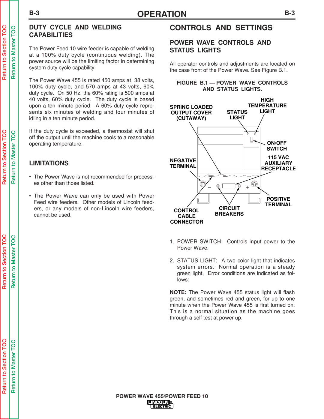
All operator controls and adjustments are located on the case front of the Power Wave. See Figure B.1.
Return to Master TOC
Return to Master TOC
The Power Wave 455 is rated 450 amps at 38 volts, 100% duty cycle, and 570 amps at 43 volts, 60% duty cycle. On 50 Hz, the 60% rating is 500 amps at 40 volts, 60% duty cycle. The duty cycle is based upon a ten minute period. A 60% duty cycle repre- sents six minutes of welding and four minutes of idling in a ten minute period.
If the duty cycle is exceeded, a thermostat will shut off the output until the machine cools to a reasonable operating temperature.
LIMITATIONS
•The Power Wave is not recommended for process- es other than those listed.
•The Power Wave can only be used with Power Feed wire feeders. Other models of Lincoln feed- ers, or any models of
FIGURE B.1 — POWER WAVE CONTROLS
AND STATUS LIGHTS.
|
| HIGH |
SPRING LOADED |
| TEMPERATURE |
OUTPUT COVER | STATUS | LIGHT |
(CUTAWAY) | LIGHT |
|
|
| ON/OFF |
|
| SWITCH |
NEGATIVE |
| 115 VAC |
| AUXILIARY | |
TERMINAL |
| |
| RECEPTACLE | |
|
| |
|
| POSITIVE |
CONTROL | CIRCUIT | TERMINAL |
| ||
BREAKERS |
| |
CABLE |
| |
|
| |
CONNECTOR |
|
|
Return to Section TOC
Return to Section TOC
Return to Master TOC
Return to Master TOC
1.POWER SWITCH: Controls input power to the Power Wave.
2.STATUS LIGHT: A two color light that indicates system errors. Normal operation is a steady green light. Error conditions are indicated as fol- lows:
NOTE: The Power Wave 455 status light will flash green, and sometimes red and green, for up to one minute when the Power Wave 455 is first turned on. This is a normal situation as the machine goes through a self test at power up.
POWER WAVE 455/POWER FEED 10
