INSTALLATION |
Return to Section TOC
Return to Section TOC
Return to Section TOC
Return to Section TOC
Return to Master TOC
Return to Master TOC
Return to Master TOC
Return to Master TOC
ELECTRODE AND WORK LEADS — ELECTRODE NEGATIVE APPLICATIONS
When negative electrode polarity is required, such as in some Innershield™ applications, install as above, except reverse the output connections at the power source (electrode cable to the negative
VOLTAGE SENSING AT THE WORK- PIECE
A
FIGURE A.4 — ELECTRODE NEGATIVE
APPLICATION.
POWER WAVE
|
|
|
|
|
|
|
|
| WIRE | |||||
|
|
|
|
| TO WORK |
|
|
| FEEDER | |||||
|
|
|
|
|
|
|
| |||||||
|
|
|
|
|
|
|
| |||||||
|
|
|
|
|
|
|
|
|
|
|
|
|
| |
|
|
|
|
|
|
|
|
|
|
|
|
|
|
|
|
|
|
|
|
|
|
|
|
|
|
|
|
|
|
|
|
|
|
|
|
|
|
|
|
|
|
|
|
|
|
|
|
|
|
|
|
|
|
|
|
|
|
|
|
|
|
|
|
|
|
|
|
|
|
|
|
|
|
|
|
|
|
|
|
|
|
|
|
|
|
|
|
|
|
|
|
|
|
|
|
|
|
|
|
|
|
|
|
|
|
|
|
|
|
|
|
|
|
|
|
|
|
|
|
|
|
|
|
|
|
|
|
|
|
|
|
|
|
|
WIRE FEEDER SETUP
WIRE DRIVE GEAR RATIO (HIGH OR LOW SPEED)
The speed range capability and drive torque of the Power Feed 10 wire drive can be easily and quickly changed by changing the external drive gear. The Power Feed 10 is shipped with both a high speed and a low speed gear. As shipped from the factory, the low speed (high torque) gear is installed on the feeder. If this is the desired gear ratio, no changes need to be made.
SELECTING THE PROPER GEAR RATIO
See the Technical Specifications at the front of this section for feed speed and wire size capabilities with high and low speed gear ratios. To determine whether you should be using the high or low speed ratio, use the following guidelines:
-If you need to operate at wire feed speeds greater than 800 IPM (20 m/m), you will need to install the high speed gear (large, 30 tooth, 1.6 inch diameter gear).
-If you need to operate at wire feed speeds less than 800 IPM (20 m/m), you should use the low speed gear (small, 20 tooth, 1.1 inch diameter gear). Using the low speed ratio will provide the maximum available wire driving force. Note: If you are feeding only small diameter wires you may, at your option, install the high speed ratio.
CHANGING THE WIRE DRIVE RATIO
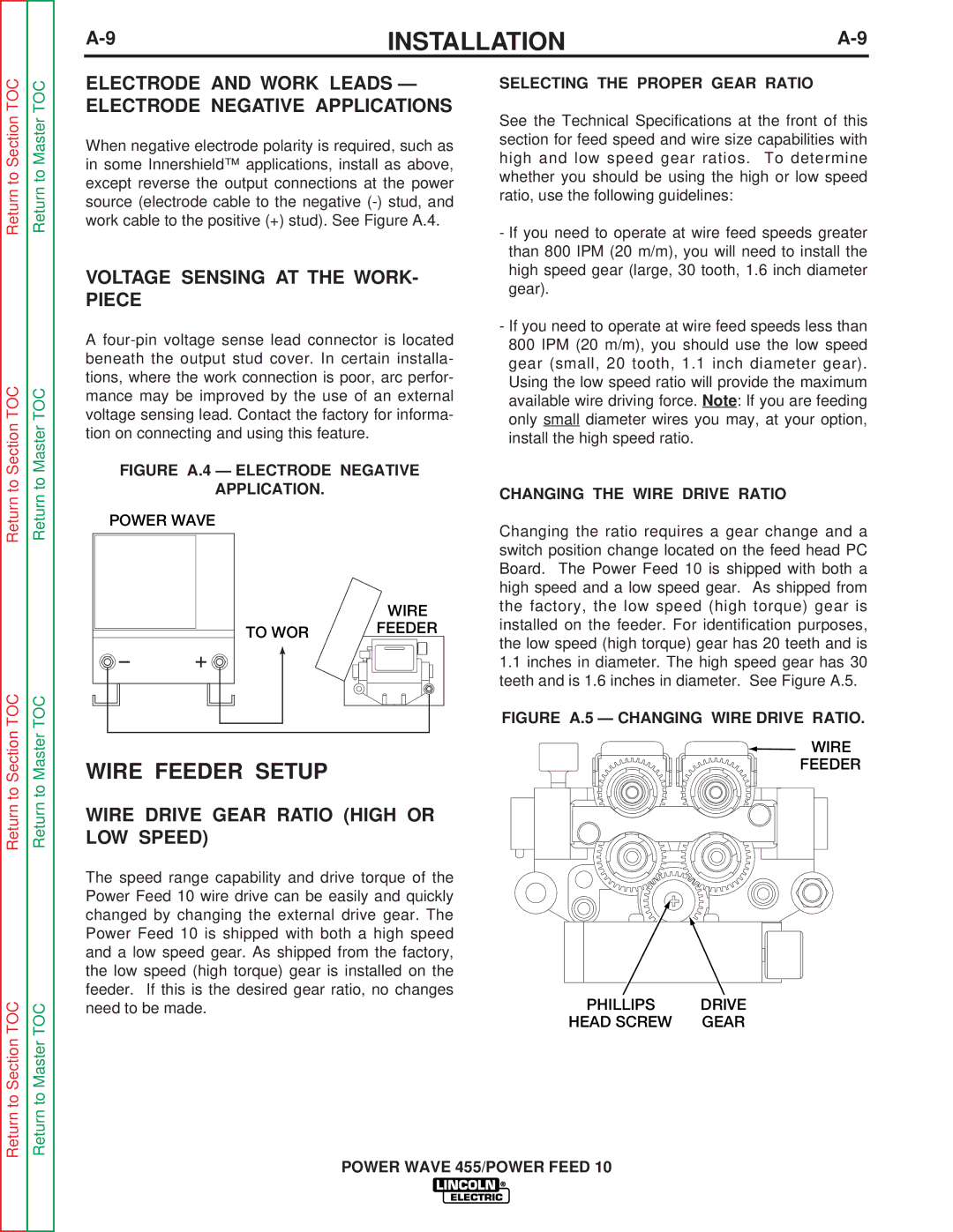
Changing the ratio requires a gear change and a switch position change located on the feed head PC Board. The Power Feed 10 is shipped with both a high speed and a low speed gear. As shipped from the factory, the low speed (high torque) gear is installed on the feeder. For identification purposes, the low speed (high torque) gear has 20 teeth and is
1.1inches in diameter. The high speed gear has 30 teeth and is 1.6 inches in diameter. See Figure A.5.
FIGURE A.5 — CHANGING WIRE DRIVE RATIO.
WIRE
FEEDER
PHILLIPS | DRIVE |
HEAD SCREW | GEAR |
