Section TOC
Master TOC
TROUBLESHOOTING AND REPAIR | ||
FLOWCHART - POWER SOURCE ERROR INTERPRETATION GUIDE |
|
|
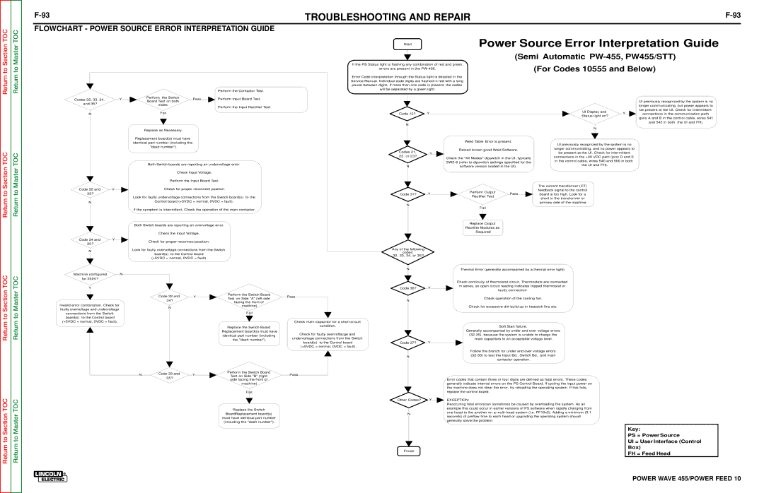
| Power Source Error Interpretation Guide |
Start |
(Semi Automatic PW-455, PW455/STT)
|
|
|
|
|
|
|
|
|
| Perform the Contactor Test. |
Codes 32, 33, 34, |
| Y |
| Perform | the Switch |
| Pass |
|
| Perform Input Board Test. |
If the PS Status light is flashing any combination of red and green,
|
|
|
|
|
|
|
|
| (For Codes 10555 and Below) |
|
|
| errors are present in the |
|
|
| |||
|
|
|
|
|
|
| |||
|
|
|
|
|
|
|
| ||
Error Code interpretation through the Status light is detailed in the |
| ||||||||
|
|
|
|
|
| ||||
Service Manual. Individual code digits are flashed in red with a long |
| ||||||||
| pause between digits. If more than one code is present, the codes |
|
| ||||||
|
|
|
|
|
| ||||
|
|
|
| will be separated by a green light. |
|
| |||
Section TOC
Master TOC
and 35? |
|
| Board Test on both | ||||||||||||||||
|
|
|
| sides. |
|
| |||||||||||||
|
|
|
|
|
|
|
| Perform the Input Rectifier Test. | |||||||||||
|
|
|
|
|
|
|
|
|
|
|
|
|
|
|
|
|
| ||
|
|
|
|
|
|
|
|
|
|
|
|
|
|
|
|
|
|
|
|
| N |
|
|
|
|
|
| Fail |
|
| |||||||||
|
|
|
|
|
|
|
|
|
|
|
|
|
|
|
|
|
|
|
|
|
|
|
|
|
|
|
|
|
|
|
|
|
|
|
|
|
|
| |
|
|
|
| Replace as Necessary. | |||||||||||||||
|
|
|
|
|
|
|
|
|
|
|
|
|
|
|
| ||||
|
|
|
|
| Replacement board(s) must have |
|
|
|
|
| |||||||||
|
|
|
|
|
|
|
|
|
|
|
|
|
| ||||||
|
|
|
| identical part number (including the |
|
|
|
| |||||||||||
|
|
|
|
|
|
|
|
|
|
|
|
|
|
|
| ||||
|
|
|
|
|
| "dash number"). | |||||||||||||
|
|
|
|
|
|
|
|
|
|
|
|
| |||||||
|
|
|
|
|
|
| Both Switch boards are reporting an undervoltage error. |
| |||||||||||
|
|
|
|
|
|
|
|
|
|
|
|
|
|
| |||||
|
|
|
|
|
|
|
|
|
| Check Input Voltage. | |||||||||
|
|
|
|
|
|
|
|
|
|
| Perform the Input Board Test. | ||||||||
|
|
|
|
|
|
|
|
|
|
| |||||||||
Code 12?
N
Codes 21, 22, or 23?
N
Y
Weld Table Error is present.
Reload known good Weld Software.
Y
Check the "All Modes" dipswitch in the UI, typically
|
|
|
|
|
|
|
|
|
| UI previously recognized by the system is no | |||||||
|
|
|
|
|
|
|
|
|
|
| longer communicating, but power appears to | ||||||
|
|
|
|
|
|
|
|
|
|
|
| be present at the UI. Check for intermittent |
| ||||
| UI Display and |
|
|
|
|
|
|
|
| ||||||||
|
|
|
| Y |
|
|
|
|
|
|
|
|
| ||||
|
|
|
|
| connections in the communication path |
|
| ||||||||||
Status light on? |
|
|
|
|
|
|
|
| |||||||||
|
|
|
|
|
|
|
|
|
|
|
| ||||||
|
|
|
|
|
|
|
|
|
|
| |||||||
|
|
|
| (pins A and B in the control cable, wires 541 | |||||||||||||
|
|
|
|
|
|
|
|
|
|
| |||||||
|
|
|
|
|
|
|
|
|
|
|
|
|
|
|
| ||
|
|
|
|
|
|
|
|
|
|
|
|
| and 542 in both the UI and FH). | ||||
|
|
|
|
|
|
|
|
|
|
|
|
|
|
|
|
|
|
|
| N |
|
|
|
|
|
|
|
|
|
|
|
| |||
UI previously recognized by the system is no longer communicating, and no power appears to be present at the UI. Check for intermittent connections in the +40 VDC path (pins D and E in the control cable, wires 540 and 500 in both the UI and FH).
Return to
Return to
Code 32 and |
| Y |
|
|
|
| Check for proper reconnect position. |
|
|
| |||
|
| ||||||||||||
33? |
|
|
|
|
|
|
|
|
|
| |||
|
|
|
|
|
|
|
|
|
| ||||
|
|
|
|
|
|
|
| Look for faulty undervoltage connections from the Switch board(s) to the |
| ||||
|
|
|
|
|
|
|
|
| Control board (+5VDC = normal, 0VDC = fault). |
| |||
| N |
|
|
|
| ||||||||
|
|
|
|
|
|
|
|
|
|
|
| ||
|
|
|
|
|
|
|
|
| |||||
|
|
|
|
|
|
|
|
|
|
|
|
|
|
|
|
|
|
|
|
|
| If the symptom is intermittent, Check the operation of the main contactor. | |||||
Both Switch boards are reporting an overvoltage error.
|
|
|
|
|
|
|
|
|
|
|
| Check the Input Voltage. |
|
|
|
|
|
|
|
|
|
|
|
|
|
|
|
|
|
|
|
| |
Code 34 and |
| Y |
|
|
|
|
|
|
|
|
|
|
| |||
35? |
|
|
|
|
| Check for proper reconnect position. |
| |||||||||
|
|
|
|
|
| |||||||||||
|
|
|
|
|
|
|
|
|
|
|
|
| ||||
|
|
|
|
|
|
|
|
|
|
|
|
| ||||
|
|
|
|
|
|
| Look for faulty overvoltage connections from the Switch | |||||||||
| N |
|
|
|
|
| ||||||||||
|
|
|
|
|
|
|
|
|
|
|
|
|
|
| ||
|
|
|
|
|
|
|
|
|
|
| board(s) to the Control board |
|
| |||
|
|
|
| |||||||||||||
|
|
|
|
|
|
|
|
|
|
| ||||||
|
|
|
|
|
|
|
|
|
| (+5VDC = normal, 0VDC = fault). |
| |||||
|
|
|
| |||||||||||||
|
|
|
|
|
|
|
|
|
|
|
|
|
|
|
|
|
|
|
|
|
|
|
|
| The current transformer (CT) | ||||
|
|
|
|
|
|
|
|
|
|
|
|
|
|
|
|
|
|
|
|
|
|
|
|
|
|
|
|
| |
|
|
|
|
|
|
|
|
|
|
|
|
|
|
|
|
|
|
|
|
|
|
|
|
| feedback signal to the control | ||||
|
|
|
|
|
|
|
|
|
|
| Perform Output |
|
|
|
| ||||||||||||||
|
|
|
|
|
|
|
|
|
|
|
|
|
|
|
|
|
|
|
|
| |||||||||
| Code 31? |
|
| Y |
|
|
|
|
| Pass |
|
|
| board is too high. Look for a |
| ||||||||||||||
|
|
|
|
|
|
|
|
|
|
|
|
|
|
|
|
|
|
|
|
| |||||||||
|
|
|
|
|
|
|
|
|
|
|
| Rectifier Test |
|
|
|
|
|
|
|
|
|
|
| ||||||
|
|
|
|
|
|
|
|
|
|
|
|
|
|
|
|
|
| ||||||||||||
|
|
|
|
|
|
|
|
|
|
|
|
|
|
|
|
|
|
|
|
| short in the transformer or |
|
| ||||||
|
|
|
|
|
|
|
|
|
|
|
|
|
|
|
|
|
|
|
|
|
|
|
|
|
|
|
| ||
|
|
|
|
|
|
|
|
|
|
|
|
|
|
|
|
|
|
|
|
|
|
|
|
|
|
| |||
|
|
|
|
|
|
|
|
|
|
|
|
|
|
|
|
|
|
|
|
|
|
|
|
|
| primary side of the machine. | |||
|
| N |
|
|
|
|
|
|
|
|
|
|
|
|
|
|
|
|
|
|
|
|
|
| |||||
|
|
|
|
|
|
|
|
|
|
|
|
|
|
|
|
|
|
|
|
|
|
|
|
|
|
| |||
|
|
|
|
|
|
|
|
|
|
|
|
|
| Fail |
|
|
|
|
|
|
|
|
|
| |||||
|
|
|
|
|
|
|
|
|
|
|
|
|
|
|
|
| |||||||||||||
|
|
|
|
|
|
|
|
|
|
|
|
|
|
|
|
|
|
|
|
|
|
|
|
|
|
|
|
|
|
|
|
|
|
|
|
|
|
|
|
|
|
|
|
|
|
|
|
|
|
|
|
|
|
|
| ||||
|
|
|
|
|
|
|
|
|
|
| Replace Output |
|
|
|
|
|
|
|
|
| |||||||||
|
|
|
|
|
|
|
|
|
|
|
|
|
|
|
|
|
|
|
|
|
|
|
| ||||||
|
|
|
|
|
|
|
|
|
| Rectifier Modules as |
|
|
|
|
|
|
|
|
| ||||||||||
|
|
|
|
|
|
|
|
|
|
|
|
|
|
|
|
|
|
|
|
|
|
|
|
| |||||
|
|
|
|
|
|
|
|
|
|
|
|
| Required |
|
|
|
|
|
|
|
|
|
| ||||||
|
|
|
|
|
|
|
|
|
|
|
|
|
|
|
|
|
|
|
|
|
|
|
|
|
|
|
|
|
|
Any of the following |
|
|
|
|
|
|
|
|
|
|
|
|
|
|
|
|
|
|
|
|
|
|
|
| |||||
| codes: |
|
|
|
|
|
|
|
|
|
|
|
|
|
|
|
|
|
|
|
|
|
|
|
| ||||
32, 33, 34, or 35? |
|
|
|
|
|
|
|
|
|
|
|
|
|
|
|
|
|
|
|
|
|
|
|
| |||||
Return to Section TOC
Section TOC
Return to Master TOC
Master TOC
|
|
|
|
|
|
|
|
|
|
|
|
|
|
|
|
|
|
|
|
|
|
|
|
|
|
|
|
|
|
|
|
| Machine configured |
|
|
|
|
| N |
|
|
|
|
|
|
|
|
|
|
|
|
|
|
|
| ||
|
|
|
| for 230V? |
|
|
|
|
|
|
|
|
|
|
|
|
|
|
|
|
|
| ||||||
|
|
|
|
|
|
|
|
|
|
|
|
|
|
|
|
|
|
|
|
|
|
|
|
|
|
|
|
|
|
|
|
|
|
|
|
|
|
|
|
|
|
|
|
|
|
|
|
|
|
|
| ||||||
|
|
|
|
| Y |
|
|
|
|
|
|
|
|
|
|
|
|
|
|
|
|
|
|
| ||||
|
|
|
|
|
|
|
|
|
|
|
|
| Code 32 and |
|
|
|
|
|
| Perform the Switch Board | ||||||||
|
|
|
|
|
|
|
|
|
|
|
|
|
|
|
| |||||||||||||
|
|
|
|
|
|
|
|
|
|
|
|
|
| Y |
|
|
|
| ||||||||||
|
|
|
|
|
|
|
|
|
|
|
|
|
|
|
|
|
| Test on Side "A" (left side | ||||||||||
|
|
|
|
|
|
|
|
|
|
| 34? |
|
|
|
|
|
| |||||||||||
|
|
|
|
|
|
|
|
|
|
|
|
|
|
|
|
| ||||||||||||
|
|
|
|
|
|
|
|
|
|
|
|
|
|
|
|
|
| facing the front of | ||||||||||
|
|
|
|
|
|
|
|
|
|
|
|
|
|
|
|
|
|
|
|
|
|
| ||||||
Invalid error combination. Check for |
|
|
|
|
|
|
|
|
|
|
|
| machine) | |||||||||||||||
|
|
|
|
|
|
|
|
|
|
|
|
|
| N |
|
|
|
|
|
|
|
|
|
|
|
|
|
|
|
|
|
|
|
|
|
|
|
|
|
|
|
|
|
|
|
|
|
|
|
|
|
|
|
| |||
| faulty overvoltage and undervoltage |
|
|
|
|
|
|
|
|
|
|
|
|
|
|
| ||||||||||||
|
|
|
|
|
|
|
|
|
|
|
|
|
|
|
|
|
|
|
|
|
|
| Fail |
| ||||
|
|
| connections from the Switch |
|
|
|
|
|
|
|
| |||||||||||||||||
|
|
|
|
|
|
|
|
|
|
|
|
|
|
|
|
|
|
|
|
|
|
|
|
|
|
|
|
|
|
|
| board(s) to the Control board |
|
|
|
|
|
|
|
|
|
|
|
|
|
|
|
|
|
|
|
| |||||
|
|
|
|
|
|
|
|
|
|
|
|
|
|
|
|
|
|
|
|
|
|
| ||||||
|
| (+5VDC = normal, 0VDC = fault). |
|
|
|
|
|
|
|
|
|
|
|
|
|
|
|
|
|
|
| |||||||
|
|
|
|
|
|
|
|
|
|
|
|
|
|
|
|
|
|
|
|
|
|
|
|
|
|
|
|
|
|
|
|
|
|
|
|
|
|
|
|
|
|
|
|
|
|
|
| Replace the Switch Board | |||||||||
|
|
|
|
|
|
|
|
|
|
|
|
|
|
|
|
|
|
|
|
|
|
|
|
|
|
| ||
|
|
|
|
|
|
|
|
|
|
|
|
|
|
|
|
|
|
| Replacement board(s) must have | |||||||||
|
|
|
|
|
|
|
|
|
|
|
|
|
|
|
|
|
|
|
|
|
|
|
|
|
|
| ||
|
|
|
|
|
|
|
|
|
|
|
|
|
|
|
|
|
|
|
| identical part number (including | ||||||||
|
|
|
|
|
|
|
|
|
|
|
|
|
|
|
|
|
|
|
|
|
|
| the "dash number"). |
| ||||
|
|
|
|
|
|
|
|
|
|
|
|
|
|
|
|
|
|
|
|
|
|
|
|
|
|
|
|
|
|
| Code 33 and |
|
|
|
|
|
| Perform the Switch Board | |||||||
N |
|
| Y |
|
|
|
| |||||||||
| 35? |
|
|
|
|
| Test on Side "B" (right | |||||||||
|
|
|
|
|
|
|
| |||||||||
|
|
|
|
|
|
|
| side facing the front of | ||||||||
|
|
|
|
|
|
|
|
| ||||||||
|
|
|
|
|
|
|
|
|
| machine) | ||||||
|
|
|
|
|
|
|
|
|
|
| ||||||
|
|
|
|
|
|
|
|
|
|
| Fail |
| ||||
|
|
|
|
|
|
|
|
|
|
|
|
|
|
|
|
|
|
|
|
|
|
|
|
|
|
|
|
|
|
|
|
| |
|
|
|
|
|
|
|
|
|
| Replace the Switch | ||||||
|
|
|
|
|
|
|
|
|
|
|
|
|
| |||
|
|
|
|
|
|
|
|
| BoardReplacement board(s) | |||||||
|
|
|
|
|
|
| must have identical part number | |||||||||
|
|
|
|
|
|
|
|
|
|
| ||||||
|
|
|
|
|
|
|
| (including the "dash number"). |
| |||||||
Pass
Check main capacitor for a short circuit
condition.
Check for faulty overvoltacge and
undervoltage connections from the Switch board(s) to the Control board
(+5VDC = normal, 0VDC = fault).
Pass
|
| N |
|
|
|
|
|
|
|
|
|
|
|
|
|
| Thermal Error (generally accompanied by a thermal error light): |
|
|
|
|
|
|
|
| |||||||||||||||||||||
|
|
|
|
|
|
|
|
|
|
|
|
|
|
|
|
|
|
|
|
|
|
|
|
|
|
|
|
|
|
|
|
|
|
|
|
|
|
|
|
|
|
|
|
|
|
|
|
|
|
|
|
|
|
|
|
|
|
|
|
|
|
|
|
|
|
|
|
|
|
|
|
|
|
|
|
|
|
|
|
|
|
|
|
|
|
|
|
|
|
|
| ||
|
|
|
|
|
|
|
|
|
|
|
|
|
|
|
|
| Check continuity of thermostat circuit. Thermostats are connected |
|
|
|
|
|
|
| ||||||||||||||||||||||
|
|
|
|
|
|
|
|
|
|
|
|
|
|
|
|
|
|
|
|
|
|
|
|
|
|
|
|
|
|
|
|
|
|
|
|
|
|
|
|
|
|
|
|
| ||
|
|
|
|
|
|
|
|
|
|
|
|
|
|
|
|
| in series, so open circuit reading indicates tripped thermostat or | |||||||||||||||||||||||||||||
|
|
|
|
|
|
|
|
| Y |
|
|
|
|
|
|
|
|
|
|
|
|
|
| |||||||||||||||||||||||
| Code 36? |
|
|
|
|
|
|
|
| |||||||||||||||||||||||||||||||||||||
|
|
|
|
|
|
|
|
|
|
|
|
|
|
|
|
|
|
|
|
|
|
|
|
|
|
|
|
|
|
|
|
|
|
|
|
|
|
|
| |||||||
|
|
|
|
|
|
|
|
|
|
|
|
|
|
|
|
|
|
|
|
|
|
|
|
|
|
|
|
| faulty connection |
|
|
|
|
|
|
|
|
|
|
|
|
|
| |||
|
|
|
|
|
|
|
|
|
|
|
|
|
|
|
| |||||||||||||||||||||||||||||||
|
|
|
|
|
|
|
|
|
|
|
|
|
|
|
|
|
|
|
|
|
|
|
|
|
|
|
|
|
|
|
|
|
|
|
|
|
|
|
|
|
|
|
|
|
|
|
|
|
|
|
|
|
|
|
|
|
|
|
|
|
|
|
|
|
|
|
|
|
|
|
| Check operation of the cooling fan. |
|
|
|
|
|
|
|
|
|
|
|
| |||||||||
|
| N |
|
|
|
|
|
|
|
|
|
|
|
| ||||||||||||||||||||||||||||||||
|
|
|
|
|
|
|
|
|
|
|
|
|
|
|
|
|
|
|
|
|
|
|
|
|
|
|
|
|
|
|
|
|
|
|
|
|
|
|
|
|
|
|
| |||
|
|
|
|
|
|
|
|
|
|
|
|
|
|
|
|
|
|
|
|
|
|
|
|
|
|
|
|
|
|
|
|
|
|
|
|
|
|
|
|
| ||||||
|
|
|
|
|
|
|
|
|
|
|
|
|
|
|
|
|
|
|
|
| Check for excessive dirt build up in heatsink fins etc. |
|
|
|
|
|
|
|
| |||||||||||||||||
|
|
|
|
|
|
|
|
|
|
|
|
|
|
|
|
|
|
|
|
|
|
|
|
|
|
|
|
|
|
|
|
|
|
|
|
|
|
|
|
|
|
| ||||
|
|
|
|
|
|
|
|
|
|
|
|
|
|
|
|
|
|
|
|
|
|
|
|
|
|
|
|
| Soft Start failure. | |||||||||||||||||
|
|
|
|
|
|
|
|
|
|
|
|
|
|
|
|
|
|
|
|
|
|
|
|
|
|
|
|
|
|
|
|
|
|
|
|
|
|
| ||||||||
|
|
|
|
|
|
|
|
|
|
|
|
|
|
|
|
|
|
|
| Generally accompanied by under and over voltage errors | ||||||||||||||||||||||||||
|
|
|
|
|
|
|
|
|
|
|
|
|
|
|
|
|
|
|
|
|
|
|
|
|
|
|
| |||||||||||||||||||
|
|
|
|
|
|
|
|
|
|
|
|
|
|
|
|
|
|
|
|
|
|
|
|
|
|
|
|
|
|
|
|
|
|
|
|
| ||||||||||
|
|
|
|
|
|
|
|
|
|
|
|
|
|
|
|
|
|
|
|
|
|
|
| main capacitors to an acceptable voltage level. |
|
|
|
|
|
|
|
|
| |||||||||||||
| Code 37? |
|
|
| Y |
|
|
|
|
|
|
|
|
|
|
|
|
|
|
|
|
|
|
|
|
|
|
|
|
|
|
|
|
|
|
|
|
|
|
|
| |||||
|
|
|
|
|
|
|
|
|
|
|
|
|
|
|
|
|
|
|
|
|
|
|
|
|
|
|
|
|
|
|
|
|
|
|
| |||||||||||
|
|
|
|
|
|
|
|
|
|
|
|
|
|
|
|
|
|
|
|
|
|
|
|
|
|
|
|
|
|
|
|
|
|
|
|
|
|
|
|
|
|
|
|
|
|
|
|
|
|
|
|
|
|
|
|
|
|
|
|
|
|
|
|
|
|
|
|
|
|
|
|
|
|
|
|
|
|
|
|
|
|
| |||||||||||
|
|
|
|
|
|
|
|
|
|
|
|
|
|
|
|
|
|
|
|
| Follow the branch for under and over voltage errors | |||||||||||||||||||||||||
|
|
|
|
|
|
|
|
|
|
|
|
|
|
|
|
|
|
|
|
|
|
|
|
|
|
|
|
|
|
|
|
|
|
| ||||||||||||
|
| N |
|
|
|
|
|
|
|
|
|
|
|
|
|
|
|
|
|
|
| |||||||||||||||||||||||||
|
|
|
|
|
|
|
|
|
|
|
|
|
|
|
|
|
|
|
|
|
|
|
|
|
|
|
|
|
|
|
|
|
|
|
|
|
|
|
|
|
|
|
| |||
|
|
|
|
|
|
|
|
|
|
|
|
|
|
|
|
|
|
|
|
| contactor operation. |
|
|
|
|
|
|
|
|
|
|
|
|
|
|
| ||||||||||
|
|
|
|
|
|
|
|
|
|
|
|
|
|
|
|
|
|
|
|
|
|
|
|
|
|
|
|
|
|
|
|
|
|
| ||||||||||||
|
|
|
|
|
|
|
|
|
|
|
|
|
|
|
|
|
|
|
|
|
|
|
|
| ||||||||||||||||||||||
|
|
|
|
|
|
|
|
|
|
|
|
|
|
| Error codes that contain three or four digits are defined as fatal errors. These codes | |||||||||||||||||||||||||||||||
|
|
|
|
|
|
|
|
|
|
|
|
|
|
|
|
|
|
|
|
|
|
|
| |||||||||||||||||||||||
|
|
|
|
|
|
|
|
|
|
|
|
|
|
| generally indicate internal errors on the PS Control Board. If cycling the input power on | |||||||||||||||||||||||||||||||
|
|
|
|
|
|
|
|
|
|
|
|
|
|
|
|
|
|
|
|
|
| |||||||||||||||||||||||||
|
|
|
|
|
|
|
|
|
|
|
|
|
|
| the machine does not clear the error, try reloading the operating system. If this fails, |
|
| |||||||||||||||||||||||||||||
|
|
|
|
|
|
|
|
|
|
|
|
|
|
|
|
|
|
|
|
| ||||||||||||||||||||||||||
|
|
|
|
|
|
|
|
|
|
|
|
|
|
| replace the control board. |
|
|
|
|
| ||||||||||||||||||||||||||
|
|
|
|
|
|
|
|
|
|
|
|
|
|
|
| |||||||||||||||||||||||||||||||
Other Codes? |
|
| Y |
|
|
| EXCEPTION: |
|
|
|
|
| ||||||||||||||||||||||||||||||||||
| ||||||||||||||||||||||||||||||||||||||||||||||
|
|
|
|
|
|
|
|
|
|
|
|
|
|
|
|
|
|
|
|
|
|
|
|
|
|
|
|
|
|
|
|
|
|
|
|
|
|
|
|
|
|
|
|
|
|
|
|
|
|
|
|
|
|
|
|
|
|
|
|
|
| Reoccuring fatal errorscan sometimes be caused by overloading the system. As an |
|
| |||||||||||||||||||||||||||||
|
|
|
|
|
|
|
|
|
|
|
|
|
|
|
|
|
|
|
| |||||||||||||||||||||||||||
|
|
|
|
|
|
|
|
|
|
|
|
|
|
| example this could occur in earlier versions of PS software when rapidly changing from | |||||||||||||||||||||||||||||||
|
|
|
|
|
|
|
|
|
|
|
|
| ||||||||||||||||||||||||||||||||||
|
|
|
|
|
|
|
|
|
|
|
|
|
|
|
|
|
|
| ||||||||||||||||||||||||||||
|
|
| N |
|
|
|
|
|
|
|
|
|
| one head to the another on a |
| |||||||||||||||||||||||||||||||
|
|
|
|
|
|
|
|
|
|
|
|
|
|
|
|
|
|
|
|
|
|
|
|
|
|
|
|
|
|
|
|
|
|
|
|
|
|
|
|
|
|
| ||||
|
|
|
|
|
|
|
|
| seconds) of preflow time to each head or upgrading the operating system shoudl |
|
|
|
|
|
| |||||||||||||||||||||||||||||||
|
|
|
|
|
|
|
|
|
|
|
|
|
|
|
|
|
|
|
|
| ||||||||||||||||||||||||||
|
|
|
|
|
|
|
|
|
|
|
|
|
|
|
| |||||||||||||||||||||||||||||||
|
|
|
|
|
|
|
|
|
|
|
|
|
|
| generally solve the problem. |
| ||||||||||||||||||||||||||||||
Return to
Return to
| Key: | ||||
|
| PS = Power Source |
| ||
|
| UI = User Interface (Control | |||
|
| Box) |
| ||
Finish |
|
|
|
| |
FH = Feed Head | |||||
| |||||