Return to Master TOC
Return to Master TOC
Return to Master TOC
Return to Master TOC
TROUBLESHOOTING AND REPAIR |
POWER WAVE
Observe all Safety Guidelines detailed throughout this manual.
PROBLEMS | POSSIBLE AREAS OF | RECOMMENDED | |||
(SYMPTOMS) | MISADJUSTMENT(S) | COURSE OF ACTION | |||
|
|
|
| ||
OUTPUT PROBLEMS (Continued) |
| ||||
|
|
|
|
|
|
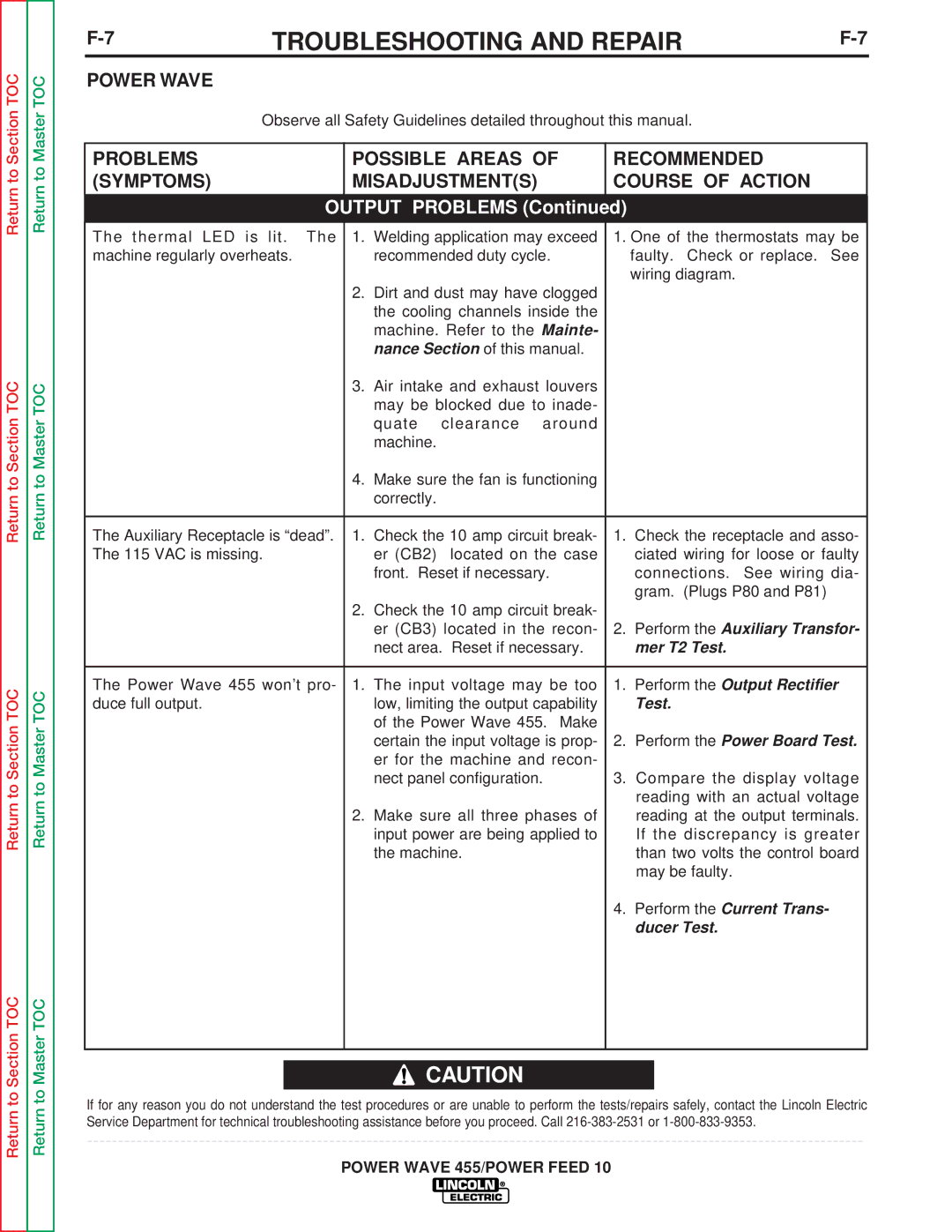
The thermal LED is lit. The | 1. | Welding application may exceed | 1. One of the thermostats may be | ||
machine regularly overheats. |
| recommended duty cycle. |
| faulty. Check or replace. See | |
|
|
|
|
| wiring diagram. |
| 2. | Dirt and dust may have clogged |
|
| |
|
| the cooling channels inside the |
|
| |
|
| machine. Refer to the Mainte- |
|
| |
|
| nance Section of this manual. |
|
| |
| 3. | Air intake and exhaust louvers |
|
| |
|
| may be blocked due to inade- |
|
| |
|
| quate | clearance around |
|
|
|
| machine. |
|
|
|
| 4. | Make sure the fan is functioning |
|
| |
|
| correctly. |
|
|
|
|
|
|
|
| |
The Auxiliary Receptacle is “dead”. | 1. | Check the 10 amp circuit break- | 1. | Check the receptacle and asso- | |
The 115 VAC is missing. |
| er (CB2) | located on the case |
| ciated wiring for loose or faulty |
|
| front. Reset if necessary. |
| connections. See wiring dia- | |
|
|
|
|
| gram. (Plugs P80 and P81) |
| 2. | Check the 10 amp circuit break- |
|
| |
|
| er (CB3) located in the recon- | 2. | Perform the Auxiliary Transfor- | |
|
| nect area. Reset if necessary. |
| mer T2 Test. | |
|
|
|
| ||
The Power Wave 455 won’t pro- | 1. | The input voltage may be too | 1. Perform the Output Rectifier | ||
duce full output. |
| low, limiting the output capability |
| Test. | |
|
| of the Power Wave 455. Make |
|
| |
|
| certain the input voltage is prop- | 2. | Perform the Power Board Test. | |
|
| er for the machine and recon- |
|
| |
|
| nect panel configuration. | 3. Compare the display voltage | ||
|
|
|
|
| reading with an actual voltage |
| 2. | Make sure all three phases of |
| reading at the output terminals. | |
|
| input power are being applied to |
| If the discrepancy is greater | |
|
| the machine. |
| than two volts the control board | |
|
|
|
|
| may be faulty. |
|
|
|
| 4. Perform the Current Trans- | |
|
|
|
|
| ducer Test. |
|
|
|
|
|
|
![]() CAUTION
CAUTION
If for any reason you do not understand the test procedures or are unable to perform the tests/repairs safely, contact the Lincoln Electric Service Department for technical troubleshooting assistance before you proceed. Call
