Return to Section TOC
Return to Section TOC
Return to Master TOC
Return to Master TOC
TROUBLESHOOTING AND REPAIR | ||
| DUAL ENCODER PC BOARD TEST (continued) |
|
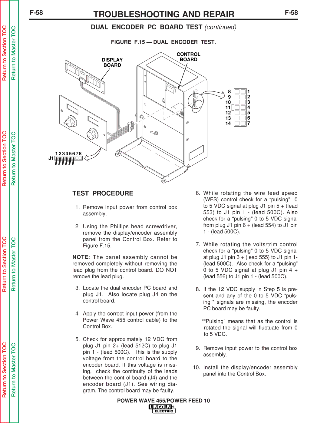
FIGURE F.15 — DUAL ENCODER TEST.
CONTROL
DISPLAYBOARD
BOARD
8 |
|
| 1 |
9 |
|
| 2 |
10 |
|
| 3 |
11 |
|
| 4 |
12 |
|
| 5 |
13 |
|
| 6 |
14 |
|
| 7 |
1 2 3 4 5 6 7 8
J1 ![]()
![]()
![]()
![]()
![]()
![]()
![]()
![]()
![]()
![]()
![]()
![]()
![]()
![]()
![]()
![]()
![]()
![]()
![]()
![]()
![]()
Return to Section TOC
Return to Section TOC
Return to Master TOC
Return to Master TOC
TEST PROCEDURE
1.Remove input power from control box assembly.
2.Using the Phillips head screwdriver, remove the display/encoder assembly panel from the Control Box. Refer to Figure F.15.
NOTE: The panel assembly cannot be removed completely without removing the lead plug from the control board. DO NOT remove the lead plug.
3.Locate the dual encoder PC board and plug J1. Also locate plug J4 on the control board.
4.Apply the correct input power (from the Power Wave 455 control cable) to the Control Box.
5.Check for approximately 12 VDC from plug J1 pin 2+ (lead 512C) to plug J1 pin 1 - (lead 500C). This is the supply voltage from the control board to the encoder board. If this voltage is miss- ing, check the continuity of the leads between the control board (J4) and the encoder board (J1). See wiring dia- gram. The control board may be faulty.
6.While rotating the wire feed speed (WFS) control check for a “pulsing” 0 to 5 VDC signal at plug J1 pin 5 + (lead
553)to J1 pin 1 - (lead 500C). Also check for a “pulsing” 0 to 5 VDC signal from plug J1 pin 6 + (lead 554) to J1 pin 1 - (lead 500C).
7.While rotating the volts/trim control check for a “pulsing” 0 to 5 VDC signal at plug J1 pin 3 + (lead 555) to J1 pin 1- (lead 500C). Also check for a “pulsing” 0 to 5 VDC signal at plug J1 pin 4 + (lead 556) to J1 pin 1 - (lead 500C).
8.If the 12 VDC supply in Step 5 is pre- sent and any of the 0 to 5 VDC “puls- ing”* signals are missing, the encoder PC board may be faulty.
*“Pulsing” means that as the control is rotated the signal will fluctuate from 0 to 5 VDC.
9.Remove input power to the control box assembly.
10.Install the display/encoder assembly panel into the Control Box.