Return to Master TOC
Return to Master TOC
Return to Master TOC
Return to Master TOC
THEORY OF OPERATION |
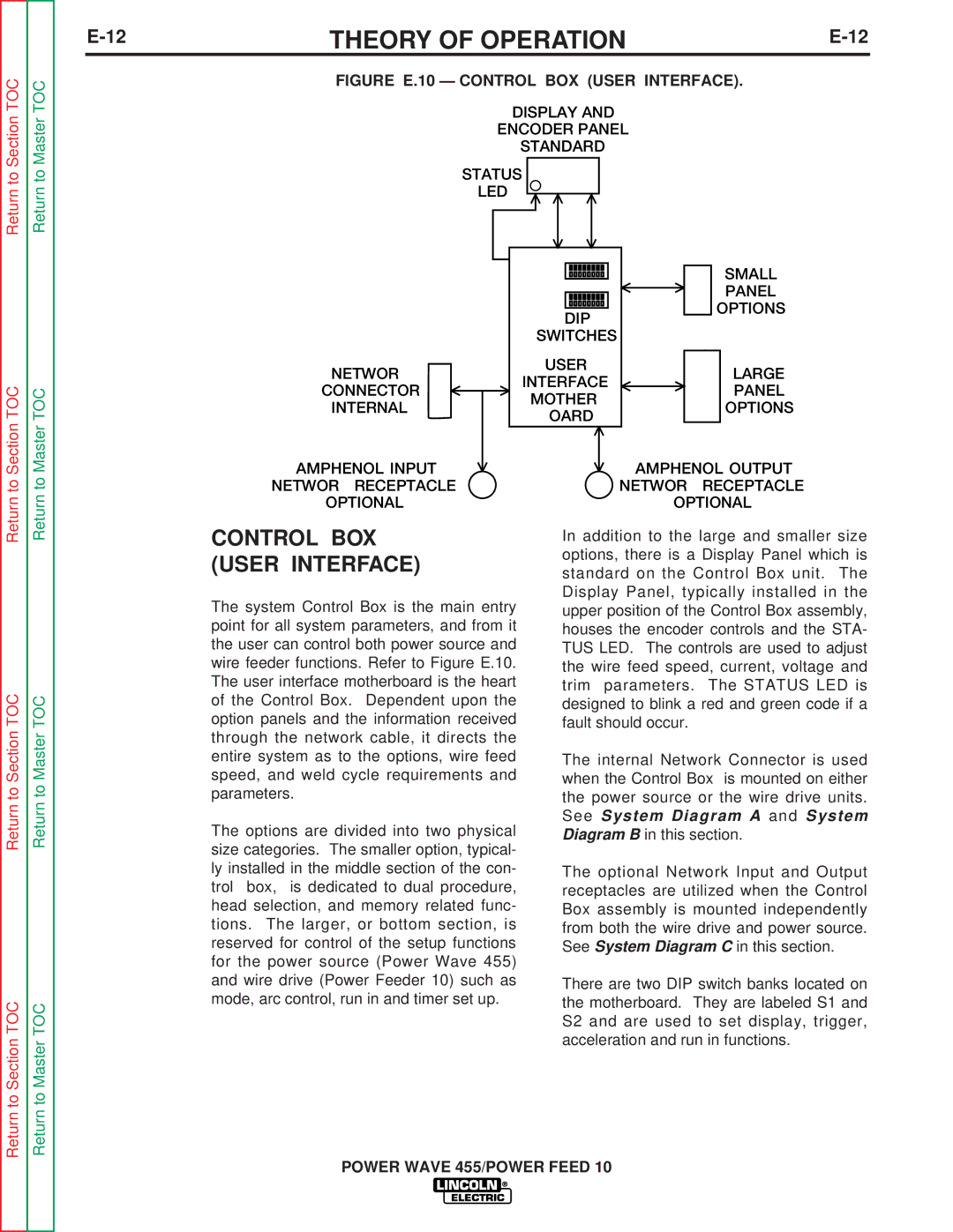
FIGURE E.10 — CONTROL BOX (USER INTERFACE).
DISPLAY AND
ENCODER PANEL
(STANDARD)
STATUS
LED
|
|
|
|
|
|
|
| SMALL | |
|
|
|
|
|
|
|
| ||
|
|
|
|
|
|
|
| PANEL | |
|
|
|
|
|
|
|
| ||
|
|
|
|
|
|
| OPTIONS | ||
|
| DIP |
|
| |||||
|
|
|
|
|
| ||||
|
| SWITCHES |
|
|
|
| |||
NETWORK |
| USER |
|
|
| LARGE | |||
|
|
|
| ||||||
| INTERFACE |
|
|
| |||||
CONNECTOR |
|
|
|
| PANEL | ||||
| MOTHER- |
|
|
| |||||
(INTERNAL) |
|
|
|
| OPTIONS | ||||
| BOARD |
|
|
| |||||
|
|
|
|
|
| ||||
|
|
|
|
|
|
|
|
| |
|
|
|
|
| |||||
NETWORK RECEPTACLE |
|
|
| NETWORK RECEPTACLE | |||||
(OPTIONAL) |
|
|
| (OPTIONAL) | |||||
CONTROL BOX | In addition to the large and smaller size | ||||||||
(USER INTERFACE) | options, there is a Display Panel which is | ||||||||
standard on the Control Box unit. The | |||||||||
|
| ||||||||
The system Control Box is the main entry | Display Panel, typically installed in the | ||||||||
upper position of the Control Box assembly, | |||||||||
point for all system parameters, and from it | houses the encoder controls and the STA- | ||||||||
the user can control both power source and | TUS LED. The controls are used to adjust | ||||||||
wire feeder functions. Refer to Figure E.10. | the wire feed speed, current, voltage and | ||||||||
The user interface motherboard is the heart | trim parameters. The STATUS LED is | ||||||||
of the Control Box. Dependent upon the | designed to blink a red and green code if a | ||||||||
option panels and the information received | fault should occur. | ||||||||
through the network cable, it directs the |
|
|
|
|
|
|
| ||
entire system as to the options, wire feed | The internal Network Connector is used | ||||||||
speed, and weld cycle requirements and | when the Control Box is mounted on either | ||||||||
parameters. | the power source or the wire drive units. | ||||||||
The options are divided into two physical | See System Diagram A and System | ||||||||
Diagram B in this section. | |||||||||
size categories. The smaller option, typical- |
|
|
|
|
|
|
| ||
ly installed in the middle section of the con- | The optional Network Input and Output | ||||||||
trol box, is dedicated to dual procedure, | receptacles are utilized when the Control | ||||||||
head selection, and memory related func- | Box assembly is mounted independently | ||||||||
tions. The larger, or bottom section, is | from both the wire drive and power source. | ||||||||
reserved for control of the setup functions | See System Diagram C in this section. | ||||||||
for the power source (Power Wave 455) |
|
|
|
|
|
|
| ||
and wire drive (Power Feeder 10) such as | There are two DIP switch banks located on | ||||||||
mode, arc control, run in and timer set up. | the motherboard. They are labeled S1 and | ||||||||
S2 and are used to set display, trigger, acceleration and run in functions.
POWER WAVE 455/POWER FEED 10