Return to Master TOC
Return to Master TOC
Return to Master TOC
Return to Master TOC
TROUBLESHOOTING AND REPAIR |
POWER FEED
Observe all Safety Guidelines detailed throughout this manual.
PROBLEMS | POSSIBLE AREAS OF | RECOMMENDED |
| ||
(SYMPTOMS) | MISADJUSTMENT(S) | COURSE OF ACTION | |||
|
|
|
|
| |
FUNCTION PROBLEMS (Continued) |
|
| |||
|
|
|
| ||
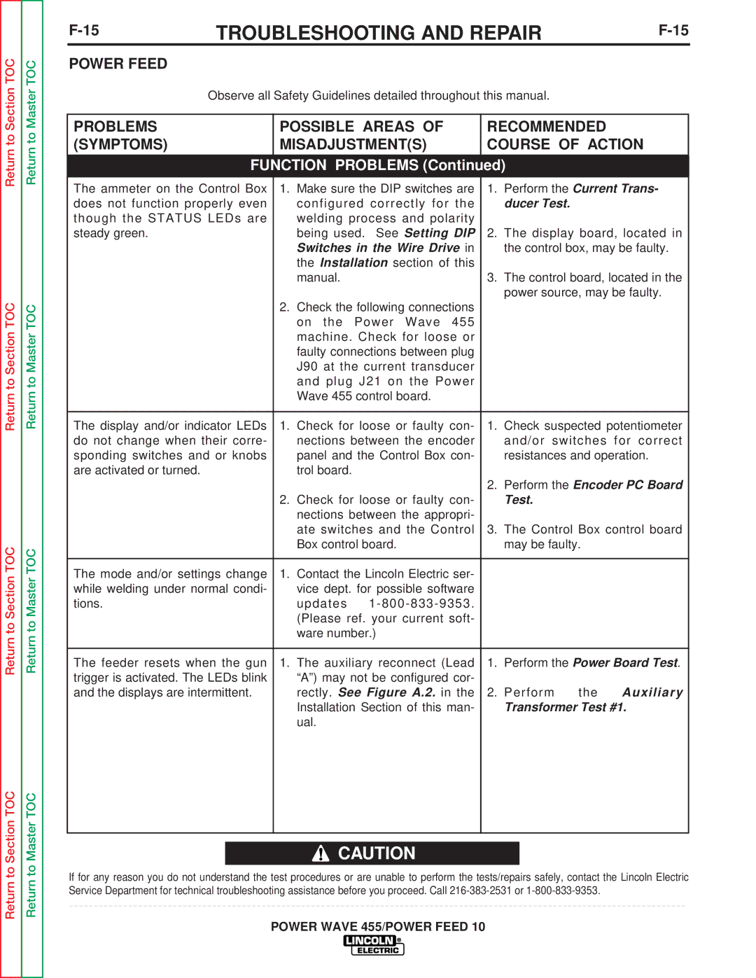
The ammeter on the Control Box | 1. Make sure the DIP switches are | 1. | Perform the Current Trans- | ||
does not function properly even | configured correctly for the |
| ducer Test. |
|
|
though the STATUS LEDs are | welding process and polarity |
|
|
|
|
steady green. | being used. See Setting DIP | 2. | The display board, located in | ||
| Switches in the Wire Drive in |
| the control box, may be faulty. | ||
| the Installation section of this |
|
|
|
|
| manual. | 3. | The control board, located in the | ||
|
|
| power source, may be faulty. | ||
| 2. Check the following connections |
|
|
|
|
| on the Power Wave 455 |
|
|
|
|
| machine. Check for loose or |
|
|
|
|
| faulty connections between plug |
|
|
|
|
| J90 at the current transducer |
|
|
|
|
| and plug J21 on the Power |
|
|
|
|
| Wave 455 control board. |
|
|
|
|
|
|
|
| ||
The display and/or indicator LEDs | 1. Check for loose or faulty con- | 1. | Check suspected potentiometer | ||
do not change when their corre- | nections between the encoder |
| and/or switches | for correct | |
sponding switches and or knobs | panel and the Control Box con- |
| resistances and operation. | ||
are activated or turned. | trol board. |
|
|
|
|
|
| 2. | Perform the Encoder PC Board | ||
| 2. Check for loose or faulty con- |
| Test. |
|
|
| nections between the appropri- |
|
|
|
|
| ate switches and the Control | 3. | The Control Box control board | ||
| Box control board. |
| may be faulty. |
| |
|
|
|
|
|
|
The mode and/or settings change | 1. Contact the Lincoln Electric ser- |
|
|
|
|
while welding under normal condi- | vice dept. for possible software |
|
|
|
|
tions. | updates |
|
|
|
|
| (Please ref. your current soft- |
|
|
|
|
| ware number.) |
|
|
|
|
|
|
|
| ||
The feeder resets when the gun | 1. The auxiliary reconnect (Lead | 1. | Perform the Power Board Test. | ||
trigger is activated. The LEDs blink | “A”) may not be configured cor- |
|
|
|
|
and the displays are intermittent. | rectly. See Figure A.2. in the | 2. | Perform | the | Auxiliary |
| Installation Section of this man- |
| Transformer Test #1. | ||
| ual. |
|
|
|
|
|
|
|
|
|
|
![]() CAUTION
CAUTION
If for any reason you do not understand the test procedures or are unable to perform the tests/repairs safely, contact the Lincoln Electric Service Department for technical troubleshooting assistance before you proceed. Call
