Return to Master TOC
Return to Master TOC
Return to Master TOC
Return to Master TOC
TROUBLESHOOTING AND REPAIR |
POWER FEED
Observe all Safety Guidelines detailed throughout this manual.
PROBLEMS | POSSIBLE AREAS OF | RECOMMENDED | |||
(SYMPTOMS) | MISADJUSTMENT(S) |
| COURSE OF ACTION | ||
|
|
| |||
FUNCTION PROBLEMS (Continued) | |||||
|
|
|
|
|
|
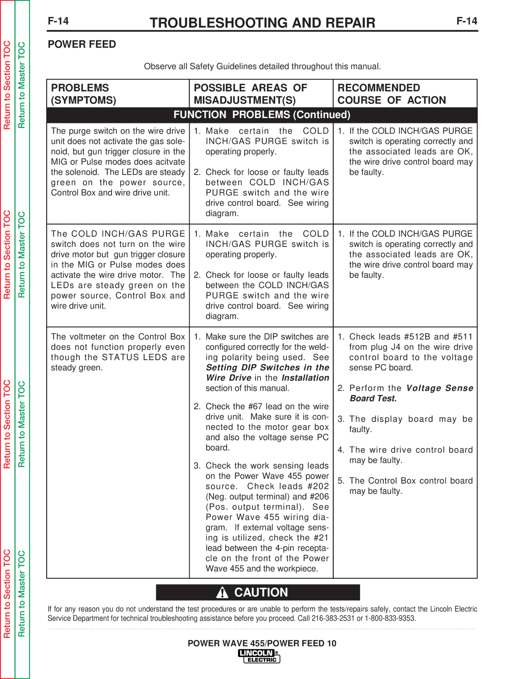
The purge switch on the wire drive | 1. Make | certain | the | COLD | 1. If the COLD INCH/GAS PURGE |
unit does not activate the gas sole- | INCH/GAS PURGE switch is | switch is operating correctly and | |||
noid, but gun trigger closure in the | operating properly. |
|
| the associated leads are OK, | |
MIG or Pulse modes does acitvate |
|
|
|
| the wire drive control board may |
the solenoid. The LEDs are steady | 2. Check for loose or faulty leads | be faulty. | |||
green on the power source, | between COLD | INCH/GAS |
| ||
Control Box and wire drive unit. | PURGE switch and the wire |
| |||
| drive control board. See wiring |
| |||
| diagram. |
|
|
|
|
|
|
|
|
|
|
The COLD INCH/GAS PURGE | 1. Make | certain | the | COLD | 1. If the COLD INCH/GAS PURGE |
switch does not turn on the wire | INCH/GAS PURGE switch is | switch is operating correctly and | |||
drive motor but gun trigger closure | operating properly. |
|
| the associated leads are OK, | |
in the MIG or Pulse modes does |
|
|
|
| the wire drive control board may |
activate the wire drive motor. The | 2. Check for loose or faulty leads | be faulty. | |||
LEDs are steady green on the | between the COLD INCH/GAS |
| |||
power source, Control Box and | PURGE switch and the wire |
| |||
wire drive unit. | drive control board. See wiring |
| |||
| diagram. |
|
|
|
|
|
|
| |||
The voltmeter on the Control Box | 1. Make sure the DIP switches are | 1. Check leads #512B and #511 | |||
does not function properly even | configured correctly for the weld- | from plug J4 on the wire drive | |||
though the STATUS LEDS are | ing polarity being used. See | control board to the voltage | |||
steady green. | Setting DIP Switches in the | sense PC board. | |||
| Wire Drive in the Installation |
| |||
| section of this manual. |
| 2. Perform the Voltage Sense | ||
| 2. Check the #67 lead on the wire | Board Test. | |||
|
| ||||
| drive unit. Make sure it is con- | 3. The display board may be | |||
| nected to the motor gear box | faulty. | |||
| and also the voltage sense PC |
| |||
| board. |
|
|
| 4. The wire drive control board |
| 3. Check the work sensing leads | may be faulty. | |||
|
| ||||
| on the Power Wave 455 power | 5. The Control Box control board | |||
| source. | Check leads #202 | |||
| may be faulty. | ||||
| (Neg. output terminal) and #206 | ||||
|
| ||||
| (Pos. output terminal). See |
| |||
| Power Wave 455 wiring dia- |
| |||
| gram. If external voltage sens- |
| |||
| ing is utilized, check the #21 |
| |||
| lead between the |
| |||
| cle on the front of the Power |
| |||
| Wave 455 and the workpiece. |
| |||
|
|
|
|
|
|
![]() CAUTION
CAUTION
If for any reason you do not understand the test procedures or are unable to perform the tests/repairs safely, contact the Lincoln Electric Service Department for technical troubleshooting assistance before you proceed. Call
