Return to Master TOC
TROUBLESHOOTING AND REPAIR |
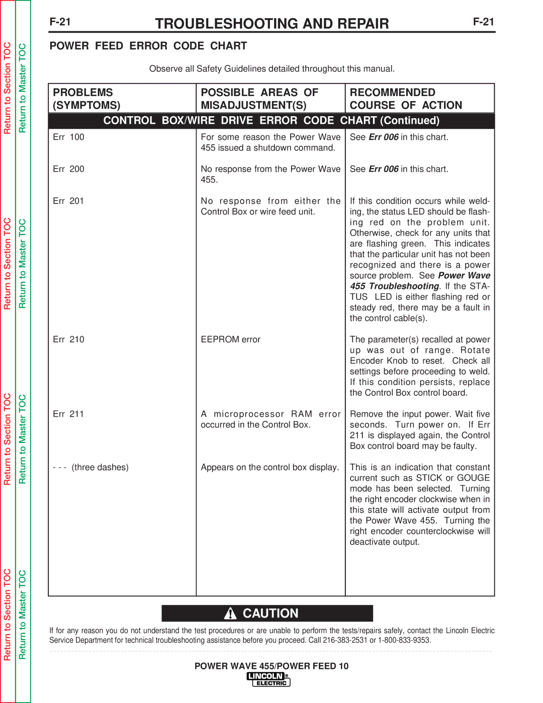
POWER FEED ERROR CODE CHART
Observe all Safety Guidelines detailed throughout this manual.
PROBLEMS | POSSIBLE AREAS OF | RECOMMENDED |
(SYMPTOMS) | MISADJUSTMENT(S) | COURSE OF ACTION |
|
|
|
CONTROL BOX/WIRE DRIVE ERROR CODE CHART (Continued)
Return to Section TOC
Return to Section TOC
Return to Master TOC
Return to Master TOC
Err 100
Err 200
Err 201
Err 210
Err 211
- - - (three dashes)
For some reason the Power Wave 455 issued a shutdown command.
No response from the Power Wave 455.
No response from either the Control Box or wire feed unit.
EEPROM error
A microprocessor RAM error occurred in the Control Box.
Appears on the control box display.
See Err 006 in this chart.
See Err 006 in this chart.
If this condition occurs while weld- ing, the status LED should be flash- ing red on the problem unit. Otherwise, check for any units that are flashing green. This indicates that the particular unit has not been recognized and there is a power source problem. See Power Wave 455 Troubleshooting. If the STA- TUS LED is either flashing red or steady red, there may be a fault in the control cable(s).
The parameter(s) recalled at power up was out of range. Rotate Encoder Knob to reset. Check all settings before proceeding to weld. If this condition persists, replace the Control Box control board.
Remove the input power. Wait five seconds. Turn power on. If Err 211 is displayed again, the Control Box control board may be faulty.
This is an indication that constant current such as STICK or GOUGE mode has been selected. Turning the right encoder clockwise when in this state will activate output from the Power Wave 455. Turning the right encoder counterclockwise will deactivate output.
Return to Master TOC
![]() CAUTION
CAUTION
If for any reason you do not understand the test procedures or are unable to perform the tests/repairs safely, contact the Lincoln Electric Service Department for technical troubleshooting assistance before you proceed. Call
