Return to Master TOC
THEORY OF OPERATION | |||||
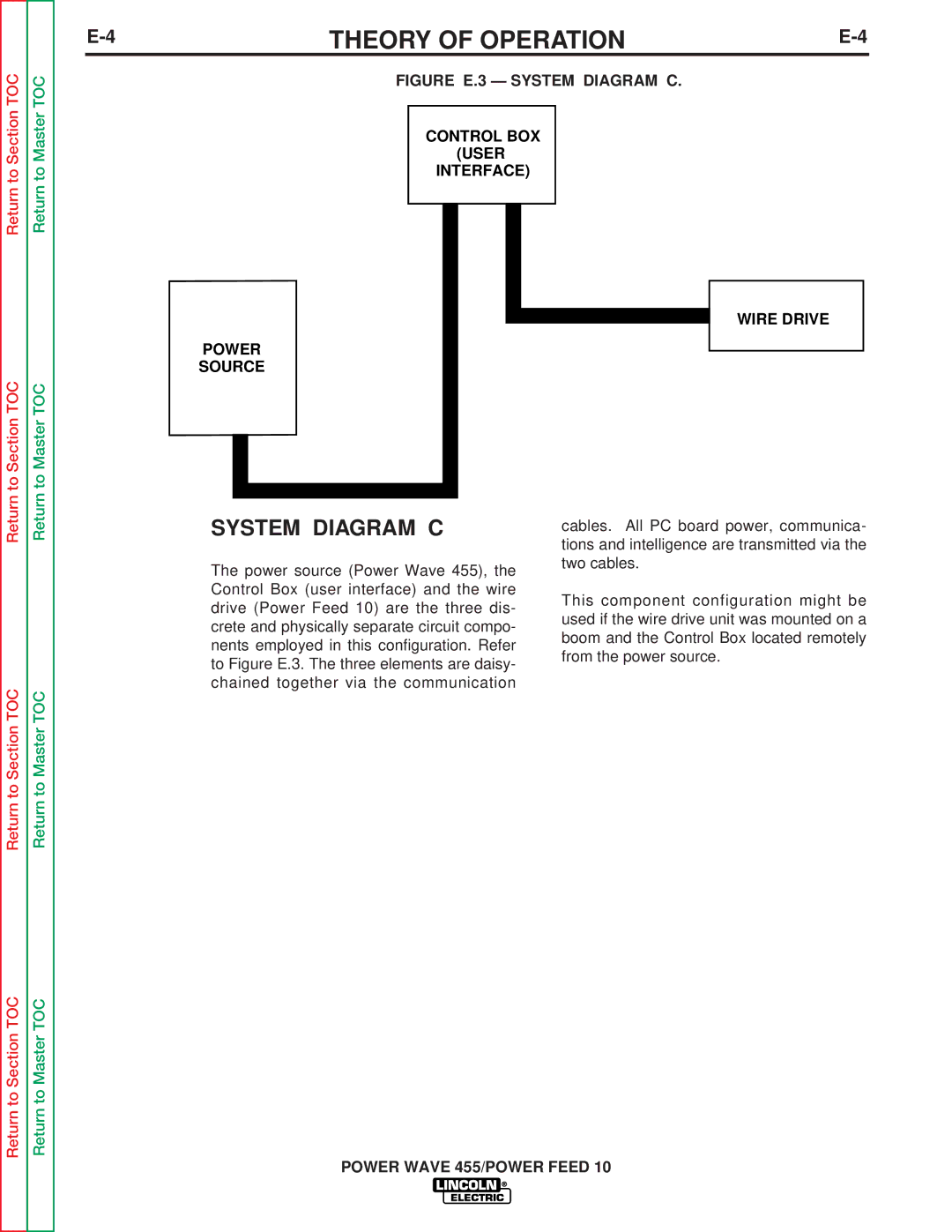
| FIGURE E.3 — SYSTEM DIAGRAM C. |
| |||
|
|
|
|
| |
|
| CONTROL BOX |
|
| |
|
| (USER |
|
| |
|
| INTERFACE) |
|
| |
|
|
|
|
|
|
|
|
|
|
|
|
WIRE DRIVE
POWER
SOURCE
Return to Master TOC
Return to Master TOC
Return to Master TOC
SYSTEM DIAGRAM C
The power source (Power Wave 455), the Control Box (user interface) and the wire drive (Power Feed 10) are the three dis- crete and physically separate circuit compo- nents employed in this configuration. Refer to Figure E.3. The three elements are daisy- chained together via the communication
cables. All PC board power, communica- tions and intelligence are transmitted via the two cables.
This component configuration might be used if the wire drive unit was mounted on a boom and the Control Box located remotely from the power source.
POWER WAVE 455/POWER FEED 10
