Return to Section TOC
Return to Section TOC
Return to Master TOC
Return to Master TOC
THEORY OF OPERATION |
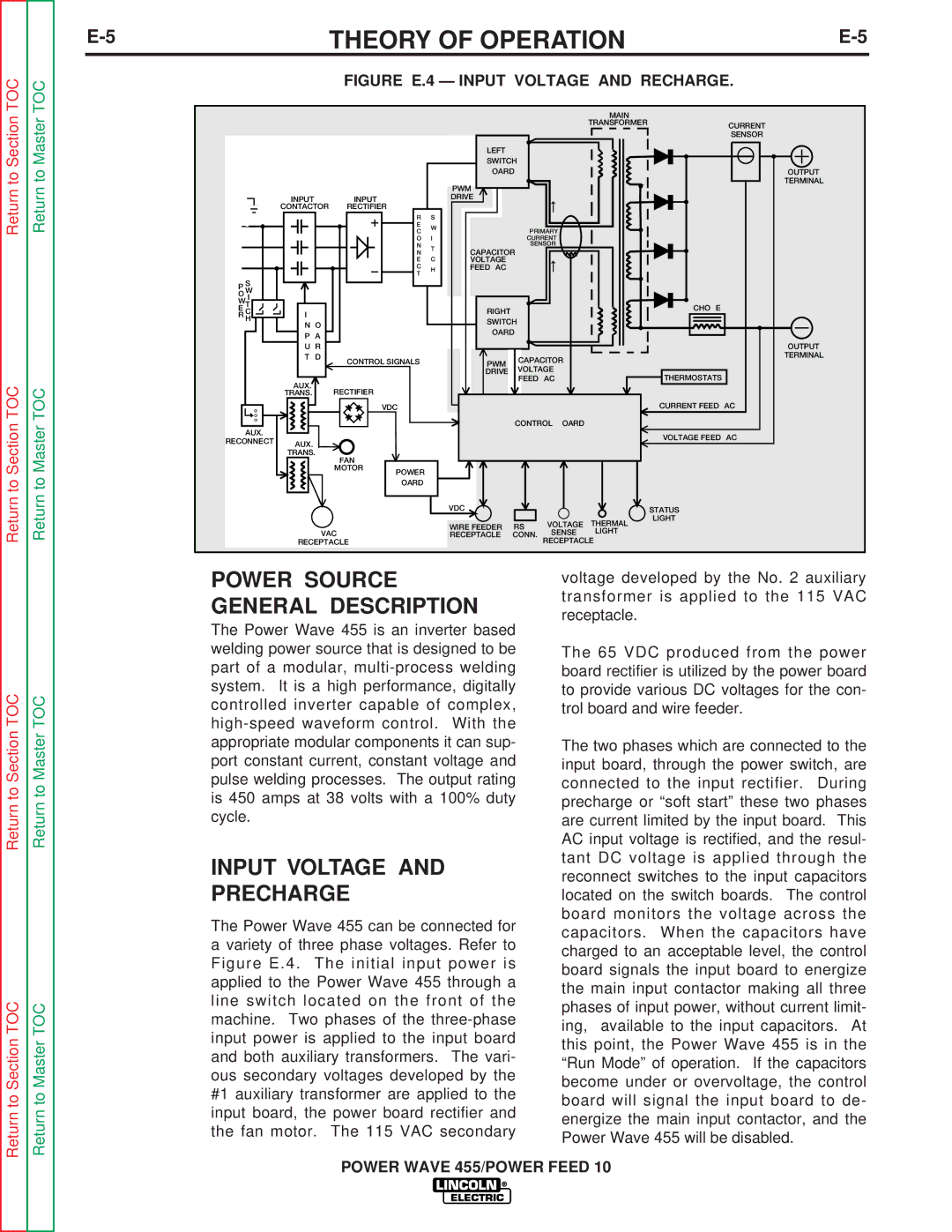
FIGURE E.4 — INPUT VOLTAGE AND RECHARGE.
|
|
|
|
|
|
|
|
| MAIN |
|
|
|
|
|
|
|
|
|
| TRANSFORMER | CURRENT |
|
|
|
|
|
|
|
|
|
| |
|
|
|
|
|
|
|
|
|
| SENSOR |
|
|
|
|
|
| LEFT |
|
|
|
|
|
|
|
|
|
| SWITCH |
|
|
| |
|
|
|
|
|
| BOARD |
|
| OUTPUT | |
|
|
|
|
|
| PWM |
|
|
| TERMINAL |
|
|
|
|
|
|
|
|
|
| |
| INPUT |
| INPUT |
|
| DRIVE |
|
|
|
|
| CONTACTOR | RECTIFIER |
|
|
|
|
|
|
| |
|
|
|
| R | S |
|
|
|
|
|
|
|
|
| E | W |
|
|
|
|
|
|
|
|
| C |
| PRIMARY |
|
| ||
|
|
|
|
|
|
|
| |||
|
|
|
| O | I |
| CURRENT |
|
| |
|
|
|
| N | T |
| SENSOR |
|
| |
|
|
|
| N | CAPACITOR |
|
|
| ||
|
|
|
|
|
|
|
| |||
|
|
|
| E | C | VOLTAGE |
|
|
|
|
|
|
|
| C | H | FEEDBACK |
|
|
|
|
|
|
|
| T |
|
|
|
| ||
|
|
|
|
|
|
|
|
|
| |
P S |
|
|
|
|
|
|
|
|
|
|
O W |
|
|
|
|
|
|
|
|
|
|
W I |
|
|
|
|
|
|
|
|
|
|
T |
|
|
|
|
| RIGHT |
|
|
| CHOKE |
E C | I | B |
|
|
|
|
|
| ||
R H |
|
|
| SWITCH |
|
|
| |||
| N O |
|
|
|
|
|
| |||
|
|
|
| BOARD |
|
|
| |||
| P A |
|
|
|
|
|
| |||
|
|
|
|
|
|
|
|
| ||
| U R |
|
|
|
|
|
|
| OUTPUT | |
| T | D | CONTROL SIGNALS |
| PWM | CAPACITOR |
| TERMINAL | ||
|
|
|
|
|
| |||||
|
|
|
|
|
| DRIVE | VOLTAGE |
| THERMOSTATS | |
| #1 AUX. |
|
|
|
|
| FEEDBACK |
| ||
|
| RECTIFIER |
|
|
|
|
|
|
| |
| TRANS. |
|
|
|
|
|
|
|
| |
|
|
| 65VDC |
|
|
|
|
| CURRENT FEEDBACK | |
|
|
|
|
|
|
| CONTROL BOARD |
|
| |
AUX. |
|
|
|
|
|
|
|
|
| VOLTAGE FEEDBACK |
RECONNECT | #2AUX. |
|
|
|
|
|
|
|
| |
|
|
|
|
|
|
|
|
| ||
|
|
|
|
|
|
|
|
|
| |
| TRANS. | FAN |
|
|
|
|
|
|
| |
|
|
|
|
|
|
|
|
|
| |
|
|
| MOTOR | POWER |
|
|
|
|
|
|
|
|
|
|
|
|
|
|
|
| |
|
|
|
| BOARD |
|
|
|
|
|
|
|
|
|
|
|
| 40VDC |
|
|
| STATUS |
|
|
|
|
|
| WIRE FEEDER | RS232 | VOLTAGE | THERMAL | LIGHT |
|
|
|
|
|
|
| ||||
| 115VAC |
|
| SENSE | LIGHT |
| ||||
|
|
| RECEPTACLE | CONN. |
| |||||
| RECEPTACLE |
|
|
|
| RECEPTACLE |
| |||
Return to Section TOC
Return to Section TOC
Return to Master TOC
Return to Master TOC
POWER SOURCE GENERAL DESCRIPTION
The Power Wave 455 is an inverter based welding power source that is designed to be part of a modular,
INPUT VOLTAGE AND PRECHARGE
The Power Wave 455 can be connected for a variety of three phase voltages. Refer to Figure E.4. The initial input power is applied to the Power Wave 455 through a line switch located on the front of the machine. Two phases of the
voltage developed by the No. 2 auxiliary transformer is applied to the 115 VAC receptacle.
The 65 VDC produced from the power board rectifier is utilized by the power board to provide various DC voltages for the con- trol board and wire feeder.
The two phases which are connected to the input board, through the power switch, are connected to the input rectifier. During precharge or “soft start” these two phases are current limited by the input board. This AC input voltage is rectified, and the resul- tant DC voltage is applied through the reconnect switches to the input capacitors located on the switch boards. The control board monitors the voltage across the capacitors. When the capacitors have charged to an acceptable level, the control board signals the input board to energize the main input contactor making all three phases of input power, without current limit- ing, available to the input capacitors. At this point, the Power Wave 455 is in the “Run Mode” of operation. If the capacitors become under or overvoltage, the control board will signal the input board to de- energize the main input contactor, and the Power Wave 455 will be disabled.
POWER WAVE 455/POWER FEED 10