| Connecting HA Servers to the Switch | CentreVu CMS R3V8 High Availability |
|
|
| Connectivity, Upgrade and Administration |
|
| Connecting to the Definity Switch |
| |
|
|
|
|
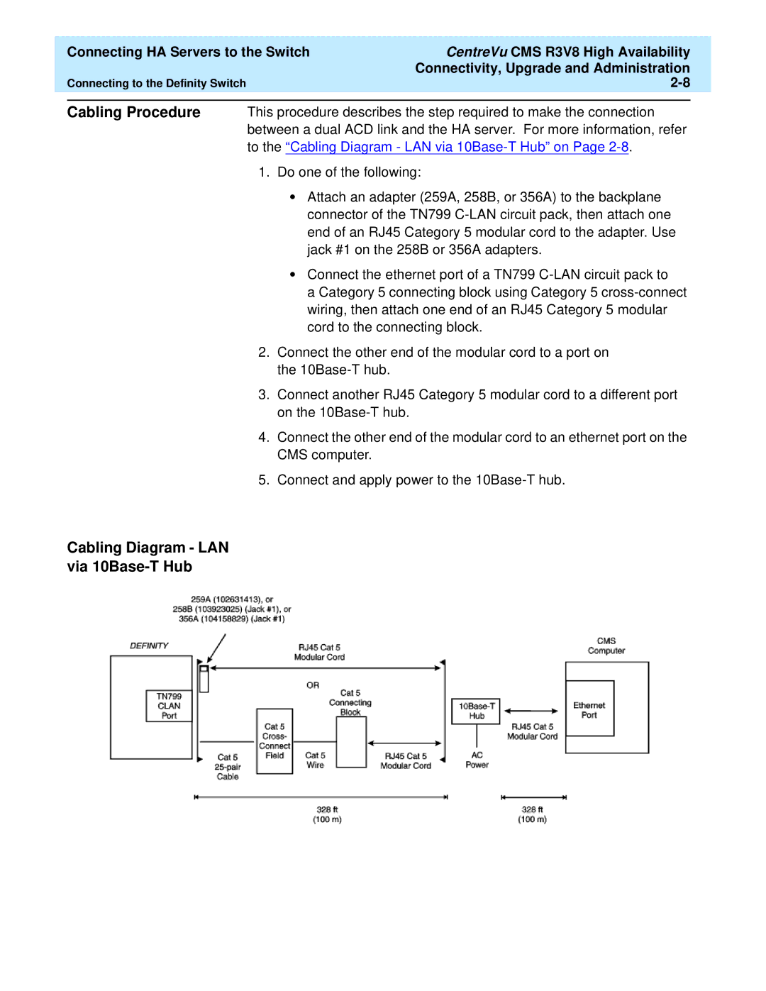
Cabling Procedure This procedure describes the step required to make the connection between a dual ACD link and the HA server. For more information, refer to the “Cabling Diagram - LAN via
1.Do one of the following:
•Attach an adapter (259A, 258B, or 356A) to the backplane connector of the TN799
•Connect the ethernet port of a TN799
a Category 5 connecting block using Category 5
2.Connect the other end of the modular cord to a port on the
3.Connect another RJ45 Category 5 modular cord to a different port on the
4.Connect the other end of the modular cord to an ethernet port on the CMS computer.
5.Connect and apply power to the
