WAN Configuration 2-5
5.For model 3341 and 3366C ADSL modems, a Wiring Type
Usually, the default AutoSense will detect the type and adjust itself accordingly. If you want to set it yourself, and you know the type of wiring you have, choose either Tip/Ring (Inner Pair) or A/A1 (Outer Pair) from the
6.Select Data Link Encapsulation and press Return. The
7.Toggle Annex Modes enabled to On only if your service provider supports it. The embedded software has the ability to support Annex M mode. However, Annex M mode may affect the training timing in some cases. Consequently, the default is Off. Not all services support this feature for all subscribers.
ATM Circuit Configuration
On ADSL WAN interfaces, the Asynchronous Transfer Mode (ATM) connection between the router and the central office equipment (DSLAM) is divided logically into one or more virtual circuits (VCs). A virtual circuit may be either a permanent virtual circuit (PVC) or a switched virtual circuit (SVC). Motorola Netopia® Routers support PVCs.
VCs are identified by a Virtual Path Identifier (VPI) and Virtual Channel Identifier (VCI). A VPI is an
•Circuits support attributes in addition to their VPI and VCI values. When configuring a circuit, you can specify an optional circuit name of up to 14 characters. The circuit name is used only to identify the circuit for management purposes as a convenience to aid in selecting circuits from lists. The default circuit name is “Circuit <n>”, where <n> is some number between one and eight corresponding to the circuit’s position in the list of up to eight circuits.
•You can also individually enable or disable a circuit without deleting it. This is useful for temporarily removing a circuit without losing the configured attributes.
•In order to function, each circuit must be bound to a Connection Profile or to the Default Profile. Among other attributes, the profile binding specifies the IP addressing information for use on the circuit. Each circuit must be bound to a distinct Connection Profile.
ATM VPI/VCI Autodetection. You can bind multiple circuits to the same Connection Profile. Motorola Netopia® Embedded Software Version 8.7.4 allows you to have a standard configuration that uses, for example, four VCs (0/35, 0/38, 8/35, 8/38) pointing to the same profile.
The unit will now automatically select the active VC on networks with a VPI/VCI of any of these four values without any custom configuration of the unit. You must, however, manually create these VCs and associate them with the profile you desire.
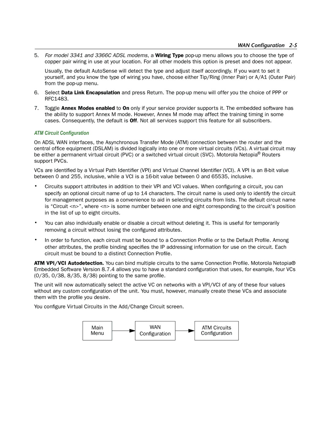
You configure Virtual Circuits in the Add/Change Circuit screen.
Main
Menu
WAN
Configuration
ATM Circuits Configuration