Switching Unit | Devices’ Features and Data Paths |
|
|
At blade start−up the Ethernet switch reads a serial PROM which contains switch configuration information such as predefined Virtual Local Area Networks (VLANs).a
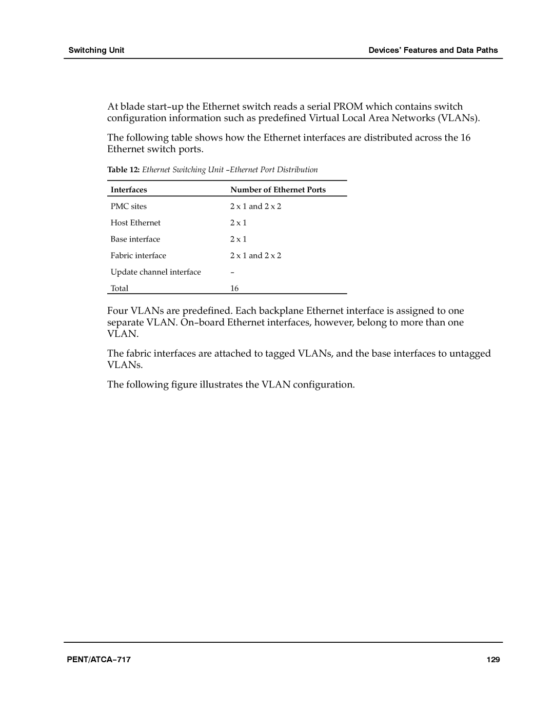
The following table shows how the Ethernet interfaces are distributed across the 16 Ethernet switch ports.a
Table 12: Ethernet Switching Unit −Ethernet Port Distribution
Interfaces | Number of Ethernet Ports |
PMC sites | 2 x 1 and 2 x 2 |
Host Ethernet | 2 x 1 |
Base interface | 2 x 1 |
Fabric interface | 2 x 1 and 2 x 2 |
Update channel interface | − |
Total | 16 |
Four VLANs are predefined. Each backplane Ethernet interface is assigned to one separate VLAN. On−board Ethernet interfaces, however, belong to more than one VLAN.a
The fabric interfaces are attached to tagged VLANs, and the base interfaces to untagged VLANs.a
The following figure illustrates the VLAN configuration.a
PENT/ATCA−717 | 129 |
