Maps and Registers | FPGA Registers |
|
|
Bit | Description | Default | Access |
4 | Select status of default and backup boot | 02 | r |
| flash write protection |
|
|
| 0: Write−protection determined by |
|
|
| on−board switches |
|
|
| 1: Write−protection determined by this |
|
|
| register |
|
|
6:5 | Indicates flash that is booted from | 002 | r |
| 002: Default boot flash |
|
|
| 012: Backup boot flash |
|
|
7 | Crisis recovery (indicates status of crisis | 12 | r |
| recovery switch) |
|
|
0: Crisis recovery
1: Normal operation
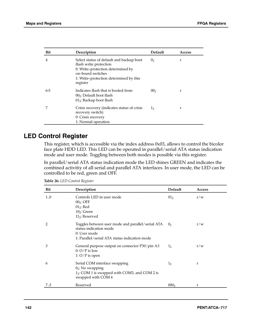
LED Control Register
This register, which is accessible via the index address 0x03, allows to control the bicolor face plate HDD LED. This LED can be operated in parallel/serial ATA status indication mode and user mode. Toggling between both modes is possible via this register.a
In parallel/serial ATA status indication mode the LED shines GREEN and indicates the combined activitiy of all serial and parallel ATA interfaces. In user mode, the LED can be controlled to be red, green and OFF.aaa
Table 26: LED Control Register
Bit | Description | Default | Access |
1..0 | Controls LED in user mode | 012 | r/w |
| 002: OFF |
|
|
| 012: Red |
|
|
| 102: Green |
|
|
| 112: Reserved |
|
|
2 | Toggles between user mode and parallel/serial ATA | 02 | r/w |
| status indication mode |
|
|
| 0: User mode |
|
|
| 1: Parallel/serial ATA status indication mode |
|
|
3 | General purpose output on connector P30/pin A3 | 12 | r/w |
| 0: O/P is low |
|
|
| 1: O/P is open |
|
|
6 | Serial COM interface swapping | 12 | r |
| 02: No swapping |
|
|
| 12: COM 1 is swapped with COM3, and COM 2 is |
|
|
| swapped with COM 4 |
|
|
7..5 | Reserved | 0002 | r |
142 | PENT/ATCA−717 |