FPGA Registers | Maps and Registers |
|
|
Address Offset | Register |
0216 | Lower data register |
0316 | Upper data register |
0416 | Clock divider register |
0516 | I2C Control and Status Register |
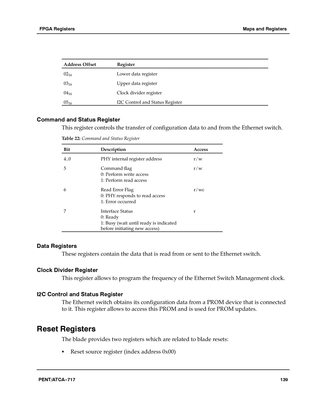
Command and Status Register
This register controls the transfer of configuration data to and from the Ethernet switch.a
Table 22: Command and Status Register
Bit | Description | Access |
4..0 | PHY internal register address | r/w |
5 | Command flag | r/w |
| 0: Perform write access |
|
| 1: Perform read access |
|
6 | Read Error Flag | r/wc |
| 0: PHY responds to read access |
|
| 1: Error occurred |
|
7 | Interface Status | r |
| 0: Ready |
|
1: Busy (wait until ready is indicated before initiating new access)
Data Registers
These registers contain the data that is read from or sent to the Ethernet switch.
Clock Divider Register
This register allows to program the frequency of the Ethernet Switch Management clock.a
I2C Control and Status Register
The Ethernet switch obtains its configuration data from a PROM device that is connected to it. This register allows to access this PROM and is used for PROM updates.a
Reset Registers
The blade provides two registers which are related to blade resets:aaaaa
SReset source register (index address 0x00)
PENT/ATCA−717 | 139 |