On−Board Connectors | Controls, Indicators, and Connectors |
|
|
|
|
| 21 17 |
| |
33 | 30 | 28 | 25 | 13 | 1 |
| 32 |
| 27 |
|
|
34 | 31 | 29 | 26 | 16 | 4 |
|
|
| 24 | 20 |
|
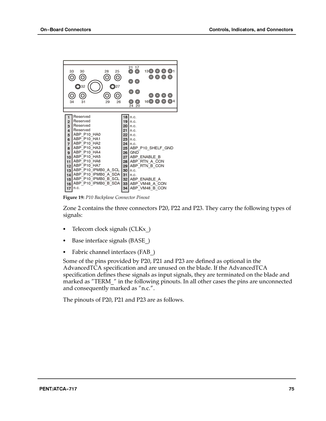
1Reserved
2Reserved
3Reserved
4Reserved
5ABP_P10_HA0
6ABP_P10_HA1
7ABP_P10_HA2
8ABP_P10_HA3
9ABP_P10_HA4
10 ABP_P10_HA5
11 ABP_P10_HA6
12 ABP_P10_HA7
13 ABP_P10_IPMB0_A_SCL 14 ABP_P10_IPMB0_A_SDA 15 ABP_P10_IPMB0_B_SCL 16 ABP_P10_IPMB0_B_SDA 17 n.c.
18n.c.
19n.c.
20n.c.
21n.c.
22n.c.
23n.c.
24n.c.
25ABP_P10_SHELF_GND
26GND
27ABP_ENABLE_B
28ABP_RTN_A_CON
29ABP_RTN_B_CON
30n.c.
31n.c.
32ABP_ENABLE_A
33ABP_VM48_A_CON
34ABP_VM48_B_CON
Figure 19: P10 Backplane Connector Pinout
Zone 2 contains the three connectors P20, P22 and P23. They carry the following types of signals:
STelecom clock signals (CLKx_)
SBase interface signals (BASE_)
SFabric channel interfaces (FAB_)
Some of the pins provided by P20, P21 and P23 are defined as optional in the AdvancedTCA specification and are unused on the blade. If the AdvancedTCA specification defines these signals as input signals, they are terminated on the blade and marked as "TERM_" in the following pinouts. In all other cases the pins are unconnected and consequently marked as "n.c.".a
The pinouts of P20, P21 and P23 are as follows.a
PENT/ATCA−717 | 75 |