Manuals
/
Motorola
/
Computer Equipment
/
Computer Accessories
Motorola
ATCA-717
manual
Pinout of the connector is as follows.a
Models:
ATCA-717
1
68
156
156
Download
156 pages
224 b
65
66
67
68
69
70
71
72
Troubleshooting
Install
Block Diagram
Error List
Connecting to the Blade
Default Configuration
Location of Reset Key
On−Board Hardware Accessories
Via Setup
Command and Status Register
Page 68
Image 68
Controls, Indicators, and Connectors
On−Board Connectors
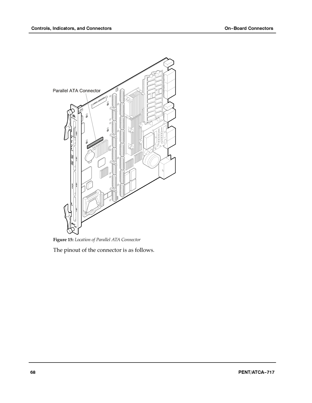
Figure 15: Location of Parallel ATA Connector
The pinout of the connector is as follows.
a
68
PENT/ATCA−717
Page 67
Page 69
Page 68
Image 68
Page 67
Page 69
Contents
PENT/ATCA−717
Copyright
Contents
Bios
Devices’ Features and Data Paths
Maps and Registers
Appendix a Troubleshooting Appendix B Battery Exchange Index
Tables
PENT/ATCA−717
Figures
Battery Exchange
Using This Guide
Conventions
Abbreviations
FCC
Revision History
PENT/ATCA−717
PENT/ATCA−717
Other Sources of Information
For further information refer to the following documents.a
Smsc
Safety Notes
Installation
Switch Settings
Operation
PMC Modules
Battery
Environment
PENT/ATCA−717
Sicherheitshinweise
EMV
Betrieb
PMC−Module
Schaltereinstellungen
Umweltschutz
Batterie
Introduction
Feedback
About this Manual
Organization of this Manual
Introduction About this Manual
Features
Standard Compliances
Order Numbers
Ordering Information
Product Nomenclature
Introduction Ordering Information
Installation
Start installation
Action Plan
Requirements
Environmental Requirements
Installation Requirements
Location of Critical Blade Temperature Spots Blade Top Side
Power Consumption
PENT/ATCA−717
Switch Settings
Location of On−board Switches
Switch Settings Installation
PENT/ATCA−717
PENT/ATCA−717
On−Board Hardware Accessories
On−Board Hardware Accessories Installation
Installation Procedure
Removal Procedure
Installing a Hard Disk
Hard Disk
CompactFlash Disk
Removing a Hard Disk
CompactFlash Installation
Location of CompactFlash Disk Connector
CMC Debug Module
Rear Transition Modules
Blade Installation
Installation into Powered Shelves
Installation in Nonpowered Shelves
Wait until the blue LED is illuminated permanently
Removal Procedure
Cable Accessory Kits
ACC/CABLE/PMC/RJ−45
Controls, Indicators, and Connectors
Face Plate
LEDs
Meaning of these LEDs is described in the following table.a
Keys
HDD
Connectors
Location of Reset Key
Their pinout is given below.a
On−Board Connectors
CompactFlash
On−Board Connectors Controls, Indicators, and Connectors
Diff. Pair
Parallel ATA Connector
PMC Sites 2 and 3 − Pn4 Connector Pinout
Pinout of the connector is as follows.a
Serial ATA Connector
Parallel ATA Connector Pinout
Location of Serial ATA Connector
CMC Module Connector
Location of CMC Connector
AdvancedTCA Backplane Connectors
PENT/ATCA−717
P10 Backplane Connector Pinout
P20 Backplane Connector Pinout − Rows E to H
P22 Backplane Connector Pinout − Rows E to H
P30 Backplane Connector Pinout − Rows a to D
P31 Backplane Connector Pinout − Rows a to D
P32 Backplane Connector Pinout − Rows E to H
Bios
Introduction
Bios
Requirements
Default Configuration
Serial Console Redirection
Connecting to the Blade
Procedure
Bios Crisis Recovery Mode
Changing Configuration Settings
Main Menu
Selecting The Boot Device
Via Setup
Via Boot Selection Menu
Boot Menu
Restoring Bios Default Settings
Procedure
Updating Bios
Bios Messages
Keyblade not working Check for correct keyblade Connection
Nvram Cmos clock Replace battery and run
Bios Post Codes
Bios
Bios
Bios
100
101
102
Devices’ Features and Data Paths
104
Block Diagram
PCI PCI−X LPC PMC I/O
CPU
Host Bridge
Host Interface
Memory Interface
Hub Interfaces
South Bridge
Interrupt Controller
Real−Time Clock
Watchdog
PCI−X Interface
Parallel ATA Interfaces
USB Interfaces
PCI Interface
Serial ATA Interfaces
Serial RS232 Interfaces
SMBus Interface
Super I/O
Serial Interfaces
Floppy Disk Interface
Keyboard/Mouse Controller
Boot Flash LPC Device ID Control
Flash Devices
Devices’ Features and Data Paths Flash Devices
Ipmc Interface
Block Transfer Interfaces
Reset Controller
Reset Types
Clock Synchronization Extensions
Port 80 Register
Miscellaneous Glue Logic
Reset Sources
Interrupt Routing Unit
Reset Mask and Source Register
Serial Interface
Flash Control Register
PMC Status Register
Intelligent Platform Management Controller
Ipmi Structure
Ipmi Temperature Sensors
Sensors
121
Atca IPMB0
I2C Addresses
Progress
Clock Synchronization Interface
Blade
125
Power Supply Module
Blade Power Supply Structure
PCI Bridge P64H2
Switching Unit
Features
Management Interface
Routing Options
Switching Unit Devices’ Features and Data Paths
PMC 1B
131
Maps and Registers
Memory Maps
Following table shows the blade′s main address map.a
Maps and Registers Memory Maps
Hardware Interrupts
PCI Devices
PCI Structure
Fpga Registers
Port 80 Register
Ethernet Switch Management Registers
Ipmi Block Transfer Interface Registers
Reset Registers
Command and Status Register
Data Registers
Clock Divider Register
Pwron
Flash Control and Status Register
LED Control Register
PMC Status Register
Shut Down Register
Clock Synchronization Interface Registers
SPI Interface Registers
Dpll Input Select and Control Register
Reference Clock Source Register
Reference Clock Divider Registers
Reference Clock Pulse Width Register
Serial Prom Update Register
Version Register
Access Control Register
Troubleshooting
Error List
Battery Exchange
Battery Exchange
Location of On−board Battery
Exchange Procedure
Remove old battery
Index
Fpga
Temperatures Critical hot spots Non−operating USB connectors
Top
Page
Image
Contents