I/O and Memory Maps | Maps and Registers |
|
|
I/O and Memory Maps
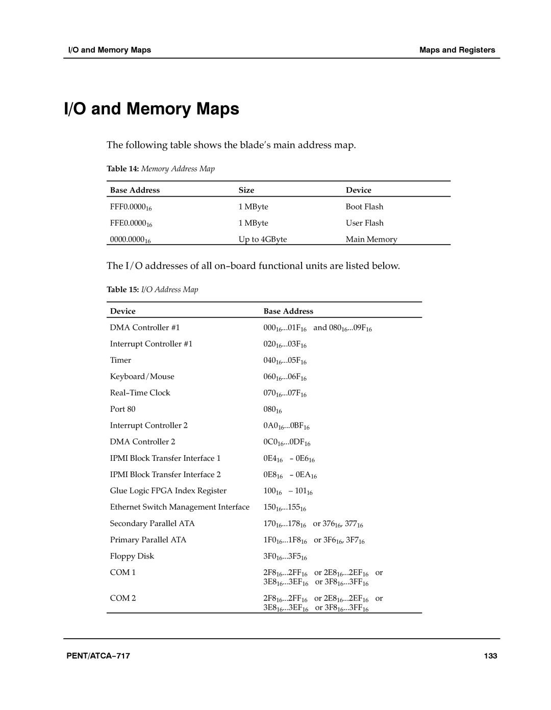
The following table shows the blade′s main address map.a
Table 14: Memory Address Map
Base Address | Size | Device |
FFF0.000016 | 1 MByte | Boot Flash |
FFE0.000016 | 1 MByte | User Flasha |
0000.000016 | Up to 4GByte | Main Memory |
The I/O addresses of all on−board functional units are listed below.aaa
Table 15: I/O Address Map
Device | Base Address |
DMA Controller #1 | 00016...01F16a and 08016...09F16 |
Interrupt Controller #1 | 02016...03F16 |
Timer | 04016...05F16 |
Keyboard/Mouse | 06016...06F16 |
Real−Time Clock | 07016...07F16 |
Port 80 | 08016 |
Interrupt Controller 2 | 0A016...0BF16 |
DMA Controller 2 | 0C016...0DF16 |
IPMI Block Transfer Interface 1 | 0E416a − 0E616 |
IPMI Block Transfer Interface 2 | 0E816a − 0EA16 |
Glue Logic FPGA Index Register | 10016a – 10116 |
Ethernet Switch Management Interface | 15016...15516 |
Secondary Parallel ATA | 17016...17816a or 37616, 37716 |
Primary Parallel ATA | 1F016...1F816a or 3F616, 3F716 |
Floppy Disk | 3F016...3F516 |
COM 1 | 2F816...2FF16a or 2E816...2EF16a or |
| 3E816...3EF16a or 3F816...3FF16 |
COM 2 | 2F816...2FF16a or 2E816...2EF16a or |
| 3E816...3EF16a or 3F816...3FF16 |
PENT/ATCA−717 | 133 |